


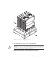

Chapter 1 Unpacking and Installing the Server 13
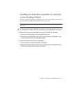
▼ To Install the Slide Rail Assemblies in the Top Position
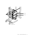
1. Remove the adjustable bracket on each rail.
a. Loosen the two nuts that secure the adjustable bracket.
b. Discard the adjustable bracket.
2. Adjust the length of each slide rail assembly.
a. Loosen the four nuts that secure the rear bracket.
b. Reposition the rear bracket to the location marked “NGR Cabinet” on the slide
rail assembly and secure the rear bracket.
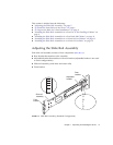
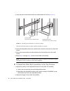
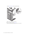
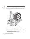
3. Insert the pins in the front bracket into cabinet holes 58 and 69 (
FIGURE 1-7).
The pins will hold the bracket in place until the bracket is secured.
4. Secure the rear bracket into cabinet holes 60 and 67 with two M-6 UNF screws.
5. Secure the front bracket into cabinet holes 60 and 67 with two M-6 UNF screws.
6. Repeat Step 1 through Step 5 for the second slide rail assembly.
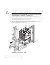
Installing the Slide Rail Assemblies in a 19-Inch 4-
Post Cabinet
The rails can be adjusted to suit a 19-inch cabinet that is compliant with either IEC
297-4 or EIA 310-D. Each slide rail assembly has a distance between front and rear
mounting rails from 17.7 to 30.7 inches (45.0 to 78.0 cm).
Note – The slide rail assemblies are reversible. They can be used on either side of
the cabinet.
Caution – It is the installer’s responsibility to ensure that the cabinet has sufficient
structural strength and stability to handle any required installations.
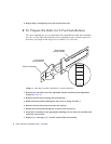
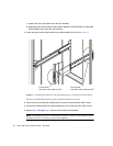
▼ To Install the Slide Rail Assemblies in a 19-Inch 4-Post
Cabinet
1. Remove the adjustable bracket on each slide rail assembly.
a. Loosen the two nuts that secure the adjustable bracket.