


vi Netra 1290 Server Installation Guide • May 2006
FIGURE 1-21 Attaching the Upper CMA Arm and Pivot Bracket 28
FIGURE 1-22 Attaching the Lower CMA Arm and Pivot Bracket 29
FIGURE 1-23 Attaching the Left-Hand T-Bracket 30
FIGURE 1-24 Attaching the Right-Hand T-Bracket 31
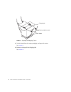
FIGURE 1-25 Attaching the Upper and Lower CMA Arms to the T-Bracket 32
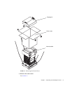
FIGURE 1-26 System Controller and I/O Assembly Locations 36
FIGURE 2-1 Netra 1290 Server On/Standby Switch 40
FIGURE A-1 External I/O Connection Locations 54
FIGURE A-2 68-Pin SCSI Connector 55
FIGURE A-3 DB-15 (Male) Alarms Service Port Connector 56
FIGURE A-4 RJ-45 Gigabit Ethernet Connectors 58
FIGURE A-5 RJ-45 TPE Socket 58
FIGURE A-6 RJ-45 Serial Connectors 60