


24 Sun Quad FastEthernet 6U CompactPCI Adapter Installation and User’s Guide • June 2000
4. If the front slot contains a factory-installed filler panel, remove the filler panel
before installing the card.
Refer to the system’s documentation for instructions on how to remove the filler
panel. Typically, you will need to loosen the filler panel’s captive screws before
removing the panel from the system.
5. Remove the card from its antistatic envelope and place it on an ESD mat (if
available) near the system.
If an ESD mat is not available, you can place the card on the antistatic envelope it
was packaged in.
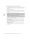
Before installing the card in the system, you will need to open the card’s ejection
levers (see
FIGURE 2-9).
6. With the card resting on the on the mat, press the levers outward to open the
ejection levers.
The card may contain different types of ejection levers. For example,
FIGURE 2-3
shows two possible types of levers. The levers may also contain a locking
mechanism that must be unlocked before you can open the levers. The ejection
levers may be different than the ones on the rear transition card.
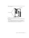
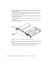
7. Lift up the card, and keeping it perfectly vertical, carefully slide the card into the
selected slot.
Be sure to align the top and bottom of the card into the slot’s card guides
(
FIGURE 2-10). Also, make sure the ejection levers remain open while you slide the
card into the slot.
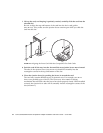
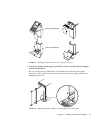
8. Push the card all the way into the slot until the two ejection levers move inward.
The tabs of the ejection levers (see
FIGURE 2-5) should fit smoothly into the
rectangular cutouts in the top and bottom of the slot.
9. Close the ejection levers by pushing the levers in toward the card.
The card may contain different types of ejection levers. For example,
FIGURE 2-6
shows two possible types of levers. The levers may also contain a locking
mechanism that will lock when the levers have been properly closed. When installed
correctly, the ejection lever tabs will fit smoothly into the rectangular cutouts of the
slot (
FIGURE 2-7).
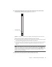
10. Using a No. 0 Phillips screwdriver, tighten the captive screws inside the card’s top
and bottom ejection levers.
The card may contain different types of ejection levers. For example,
FIGURE 2-8
shows two possible types of levers.
11. Remove the wrist strap from the chassis and from your wrist.
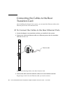
After installing the adapter, see “Connecting the Cables to the Rear Transition Card”
on page 26 for instructions on connecting the cables to the rear card.