Grid Connection
The Solar Inverter must be connected to
the grid with five-cores (L1, L2, L3, N, PE).
We recommend a cable cross-section of
5 x 4 mm
2
.
The Solar Inverter is connected to the
supply grid via its internal printed-circuit
board terminals.
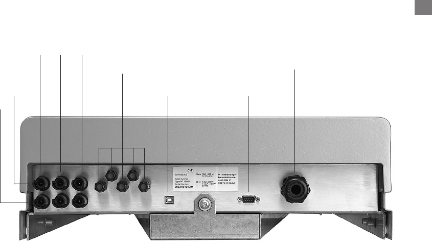
DC1 DC2 DC3 AC wiring loom
L1, L2, L3, N, PE
Illustr.: Entry openings on the underside of the device
RS232
Alarm relais, RS485 (in and out),
irradiation sensor with integrated
temperature measurement
USB
As an input-to-grid line protection ele-
ment, we recommend using a 3 x 25 A
automatic circuit breaker for the NT
10000. No consumers may be connected
to the supply line from the Solar Inverter
to the automatic circuit breaker. The Solar
Inverter injects in three phases via termi-
nals L1, L2, and L3. Please mind the pin
assignment. A wrong assignment may
destroy the device.
109
DC+
DC–
GB
BP13370_NT_10000_englisch 23.11.2005 17:40 Uhr Seite 25


