


Chapter 2: Installation
2-13
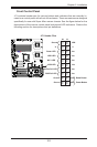
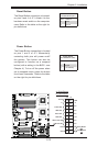
Power Button
OH/Fan Fail LED
1
NIC1 LED
Reset Button
2
HDD LED
Power LED
Reset
PWR
Vcc
Vcc
Vcc
Vcc
Ground
Ground
1920
Vcc
X
Ground
NMI
X
Vcc
PWR Fail LED
NIC2 LED
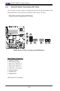
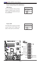
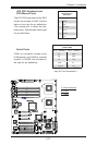
Power Button
The Power Button connection is located
on pins 1 and 2 of JF1. Momentarily
contacting both pins will power on/off
the system. This button can also be
configured to function as a suspend
button (with a setting in the BIOS - see
Chapter 4). To turn off the power when
set to suspend mode, press the button
for at least 4 seconds. Refer to the table
on the right for pin denitions.
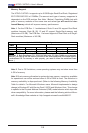
Power Button
PinDenitions(JF1)
Pin# Denition
1 Signal
2 +3V Standby
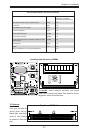
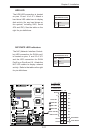
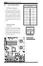
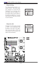
Reset Button
The Reset Button connection is located
on pins 3 and 4 of JF1. Attach it to the
hardware reset switch on the computer
case. Refer to the table on the right for
pin denitions.
Reset Button
PinDenitions(JF1)
Pin# Denition
3 Reset
4 Ground
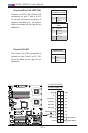
A. Reset Button
B. PWR Button
A
B
X7DCL-3/i