


2-20
X7DCL-3/X7DCL-i User's Manual
JBT1
DIMM2A
SP1
JI2C1
JI2C2
JL1
LED5
LED6
LED3
JWD1
JPG1
JPL2
JPA1
Fan 4
JD1
LED4
JWOL1
JPWF1
JAR
8-Pin PWR
I-Button
LAN
CTRL
VGA
CTRL
S I/O
SATA4
SATA3
SATA2
SATA1
SATA0
SATA5
SATA-GPIO0
Battery
SAS0
SAS1
SAS2
SAS3
SAS4
SAS5
SAS6
SAS7
PWR LED
JP1
JP2
COM2
JWOR1
JKEY1
Buzzer
BIOS
SATA-GPIO1
ITE
CTRL
LAN
CTRL
DIMM1A
DIMM2B
DIMM1B
DIMM2C
DIMM1C
LED1
SAS-GPIO0
SAS-GPIO1
24-Pin PWR
JPA2
System Status LED
Fan 1
CPU1 VRM OH LED
CPU2 VRM OH LED
Floppy
IDE
BPI
2
C
USB2/3
SMB_PS
KB/MS
COM1
VGA
FAN6
Slot4 PCI-E x4(in x8 slot)
Slot1 PCI 33MHz
SIMLC
USB0/1
LAN1
LAN2
FAN5
CPU1
CPU2
Fan 2
Fan 3
FP CTRL
USB4/5
Slot2 PCI 33MHz
Slot3 PCI 33MHz
Slot5 PCI-E x8
Slot6 PCI-E x8
Intel
5100
North Bridge
South Bridge
ICH9R
Intel
LSI
SAS
CTRL
JPL1
X7DCL-3/i
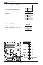
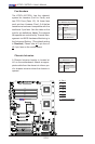
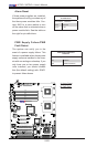
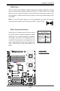
Alarm Reset
If three power supplies are installed,
the system will notify you when any of
the three power modules fails. Con-
nect JAR1 to a micro-switch to turn
off the alarm that is activated when a
power module fails. See the table on
the right for pin denitions.
Alarm Reset
PinDenitions
Pin Setting Denition
Pin 1 Ground
Pin 2 +5V
A
A. Alarm Reset
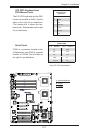
B. PWR Fault
B
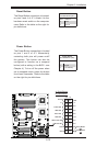
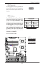
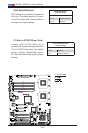
PWR Supply Failure/PWR
Fault Detect
The system can notify you in the
event of a power supply failure. This
feature is available when three power
supply units are installed in the chas-
sis with one acting as a backup. If you
only have one or two power supply
units installed, you should disable
this (the default setting) with JPWF1
to prevent false alarms.
PWR Supply PWR Fault
Connector
Jumper Setting Denition
On Enabled
Off Disabled (Default)