


2-16
X7DCL-3/X7DCL-i User's Manual
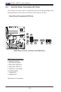
JBT1
DIMM2A
SP1
JI2C1
JI2C2
JL1
LED5
LED6
LED3
JWD1
JPG1
JPL2
JPA1
Fan 4
JD1
LED4
JWOL1
JPWF1
JAR
8-Pin PWR
I-Button
LAN
CTRL
VGA
CTRL
S I/O
SATA4
SATA3
SATA2
SATA1
SATA0
SATA5
SATA-GPIO0
Battery
SAS0
SAS1
SAS2
SAS3
SAS4
SAS5
SAS6
SAS7
PWR LED
JP1
JP2
COM2
JWOR1
JKEY1
Buzzer
BIOS
SATA-GPIO1
ITE
CTRL
LAN
CTRL
DIMM1A
DIMM2B
DIMM1B
DIMM2C
DIMM1C
LED1
SAS-GPIO0
SAS-GPIO1
24-Pin PWR
JPA2
System Status LED
Fan 1
CPU1 VRM OH LED
CPU2 VRM OH LED
Floppy
IDE
BPI
2
C
USB2/3
SMB_PS
KB/MS
COM1
VGA
FAN6
Slot4 PCI-E x4(in x8 slot)
Slot1 PCI 33MHz
SIMLC
USB0/1
LAN1
LAN2
FAN5
CPU1
CPU2
Fan 2
Fan 3
FP CTRL
USB4/5
Slot2 PCI 33MHz
Slot3 PCI 33MHz
Slot5 PCI-E x8
Slot6 PCI-E x8
Intel
5100
North Bridge
South Bridge
ICH9R
Intel
LSI
SAS
CTRL
JPL1
X7DCL-3/i
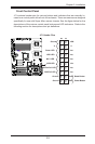
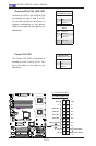
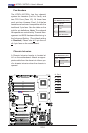
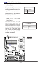
Fan Headers
The X7DCL-3/X7DCL-i has four chassis/
system fan headers (Fan3 to Fan6), and
two CPU Fans (Fans 1/2). All these fans
are 4-pin fans. However, Pins 1-3 of the fan
headers are backward compatible with the
traditional 3-pin fans. See the table on the
right for pin denitions. Note: The onboard
fan speeds are controlled by Thermal Man-
agement via BIOS Hardware Monitoring in
the Advanced Setting. (The default setting
is Disabled.) Please use all 3-pin fans or
all 4-pin fans on the motherboard.
Fan Header
PinDenitions(Fan1-6)
Pin# Denition
1 Ground
2 +12V
3 Tachometer
4 PWR Modulation
B
C
G
F
E
D
A
A. Fan 1
B. Fan 2
C. Fan 3
D. Fan 4
E. Fan 5
F. Fan 6
G. Chassis Intrusion
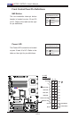
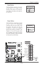
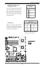
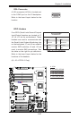
Chassis Intrusion
A Chassis Intrusion header is located at
JL1 on the motherboard. Attach an appro-
priate cable from the chassis to inform you
of a chassis intrusion when the chassis is
opened.
Chassis Intrusion
PinDenitions(JL1)
Pin# Denition
1 Intrusion Input
2 Ground