


Chapter 2: Installation
2-25
JBT1
DIMM2A
SP1
JI2C1
JI2C2
JL1
LED5
LED6
LED3
JWD1
JPG1
JPL2
JPA1
Fan 4
JD1
LED4
JWOL1
JPWF1
JAR
8-Pin PWR
I-Button
LAN
CTRL
VGA
CTRL
S I/O
SATA4
SATA3
SATA2
SATA1
SATA0
SATA5
SATA-GPIO0
Battery
SAS0
SAS1
SAS2
SAS3
SAS4
SAS5
SAS6
SAS7
PWR LED
JP1
JP2
COM2
JWOR1
JKEY1
Buzzer
BIOS
SATA-GPIO1
ITE
CTRL
LAN
CTRL
DIMM1A
DIMM2B
DIMM1B
DIMM2C
DIMM1C
LED1
SAS-GPIO0
SAS-GPIO1
24-Pin PWR
JPA2
System Status LED
Fan 1
CPU1 VRM OH LED
CPU2 VRM OH LED
Floppy
IDE
BPI
2
C
USB2/3
SMB_PS
KB/MS
COM1
VGA
FAN6
Slot4 PCI-E x4(in x8 slot)
Slot1 PCI 33MHz
SIMLC
USB0/1
LAN1
LAN2
FAN5
CPU1
CPU2
Fan 2
Fan 3
FP CTRL
USB4/5
Slot2 PCI 33MHz
Slot3 PCI 33MHz
Slot5 PCI-E x8
Slot6 PCI-E x8
Intel
5100
North Bridge
South Bridge
ICH9R
Intel
LSI
SAS
CTRL
JPL1
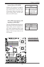
X7DCL-3/i
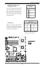
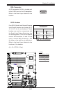
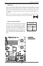
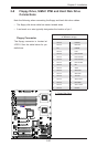
CMOS Clear
JBT1 is used to clear CMOS. Instead of pins, this "jumper" consists of contact
pads to prevent the accidental clearing of CMOS. To clear CMOS, use a metal
object such as a small screwdriver to touch both pads at the same time to short
the connection. Always remove the AC power cord from the system before clear-
ing CMOS.
Note: For an ATX power supply, you must completely shut down the system,
remove the AC power cord and then short JBT1 to clear CMOS.
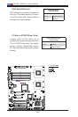
A
B
A. Clear CMOS
B. Watch Dog Enable
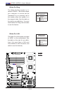
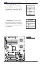
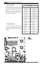
Watch Dog Enable/Disable
Watch Dog is a system monitor that can reboot
the system when a software application hangs.
Close pins 1-2 to reset the system if an applica-
tion hangs. Close pins 2-3 to generate a non-
maskable interrupt signal for the application that
hangs. See the table on the right for jumper set-
tings. Watch Dog must also be enabled in the
BIOS.
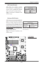
Watch Dog
Jumper Settings
Jumper Setting Denition
Pins 1-2 Reset
(default)
Pins 2-3 NMI
Open Disabled