


2-14
X7DCL-3/X7DCL-i User's Manual
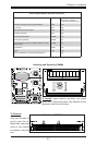
JBT1
DIMM2A
SP1
JI2C1
JI2C2
JL1
LED5
LED6
LED3
JWD1
JPG1
JPL2
JPA1
Fan 4
JD1
LED4
JWOL1
JPWF1
JAR
8-Pin PWR
I-Button
LAN
CTRL
VGA
CTRL
S I/O
SATA4
SATA3
SATA2
SATA1
SATA0
SATA5
SATA-GPIO0
Battery
SAS0
SAS1
SAS2
SAS3
SAS4
SAS5
SAS6
SAS7
PWR LED
JP1
JP2
COM2
JWOR1
JKEY1
Buzzer
BIOS
SATA-GPIO1
ITE
CTRL
LAN
CTRL
DIMM1A
DIMM2B
DIMM1B
DIMM2C
DIMM1C
LED1
SAS-GPIO0
SAS-GPIO1
24-Pin PWR
JPA2
System Status LED
Fan 1
CPU1 VRM OH LED
CPU2 VRM OH LED
Floppy
IDE
BPI
2
C
USB2/3
SMB_PS
KB/MS
COM1
VGA
FAN6
Slot4 PCI-E x4(in x8 slot)
Slot1 PCI 33MHz
SIMLC
USB0/1
LAN1
LAN2
FAN5
CPU1
CPU2
Fan 2
Fan 3
FP CTRL
USB4/5
Slot2 PCI 33MHz
Slot3 PCI 33MHz
Slot5 PCI-E x8
Slot6 PCI-E x8
Intel
5100
North Bridge
South Bridge
ICH9R
Intel
LSI
SAS
CTRL
JPL1
X7DCL-3/i
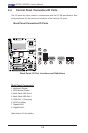
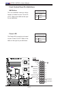
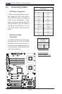
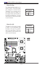
2-5 Connecting Cables
ATX Power Connector
A 24-pin main power supply connec-
tor is located at JPW2, and an 8-pin
CPU PWR connector is locatged at
JPW1 on the motherboard. These
power connectors meet the SSI EPS
12V specication. See the table on
the right for pin denitions. For the
8-pin PWR (JPW1), refer to the item
below.
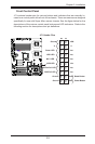
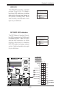
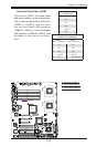
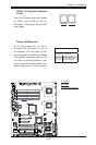
Processor Power
Connector
In addition to the Primary ATX power
connector, the 12V 8-pin CPU PWR
connector at JPW1 must also be con-
nected to provide adequate power to
your processors. See the table on the
right for pin denitions.
ATX Power 24-pin Connector
PinDenitions
Pin# Denition Pin # Denition
13 +3.3V 1 +3.3V
14 -12V 2 +3.3V
15 COM 3 COM
16 PS_ON 4 +5V
17 COM 5 COM
18 COM 6 +5V
19 COM 7 COM
20 Res (NC) 8 PWR_OK
21 +5V 9 5VSB
22 +5V 10 +12V
23 +5V 11 +12V
24 COM 12 +3.3V
Required Connection
12V 8-pin Power CPU
Connector
PinDenitions
Pins Denition
1 through 4 Ground
5 through 8 +12V
A. 24-pin ATX PWR
B. 8-pin Processor PWR
A
B