


D14128.02—NOVEMBER 2008
22
Codec C90
System Integrator Guide
Contents Introduction Getting Started Interfaces About the API xConfiguration xCommand xStatus Cameras Appendices Contact us
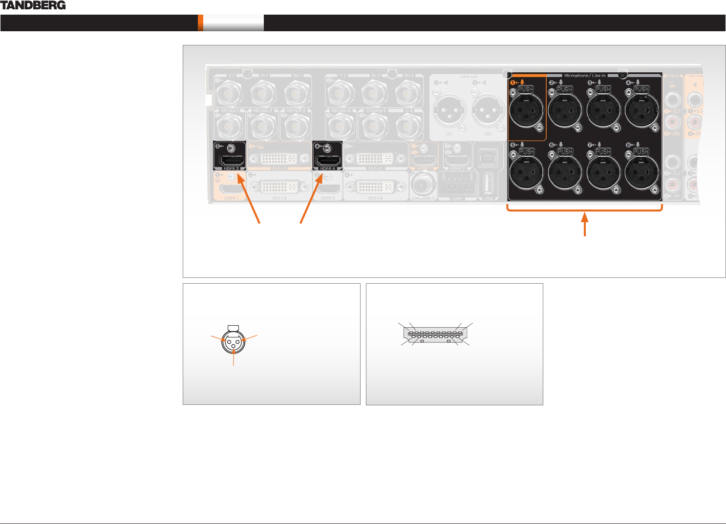
Interfaces
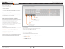
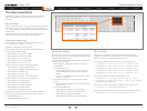
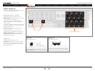
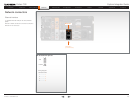
Audio inputs (I)
Unused, but connected audio inputs should be set
to Off to avoid unwanted audio/noise.
Microphone/Line In 1–8 (XLR)
8 x Balanced XLR sockets, audio input 1–8.
Main connector. The Microphone/Line In 1 is the
main connector for the microphone.
All eight microphone inputs are for balanced
electret microphones, 48V phantom powered via
XLR connectors.
The phantom powering of all eight XLR sockets can
be individually switched off. The input will then be a
balanced line level input.
All Microphone/Line In 1–8 are equipped with
acoustic echo canceller.
Use Microphone/Line In 1–8 to connect to an
external microphone amplifier or an external mixer.
Default configuration. In default configuration,
all Microphone/Line In inputs are enabled and
configured as microphones.
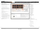
HDMI In 3, 4
2 x HDMI connectors, audio input 3, 4
Typical use. Use HDMI In 3 or 4 (2–8 channels)
to connect to external playback devices as DVD
players. Each input support up to two channels at
48kHz sampling rate.
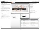
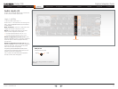
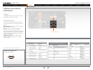
XLR pin-out
External view of socket
Pin 1: Gnd
Pin 2: Hot
Pin 3: Cold/neutral
12
3
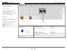
8 x Microphone /Line In
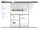
2 x HDMI In
XLR - Electrical Connector (Cannon XL series with
Rubber compound)
Pin: 19 17 3 1
Pin: 18 16 4 2
HDMI pin-out
External view of socket
Please refer to previous page for pin-out scheme.