


D14128.02—NOVEMBER 2008
36
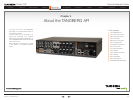
Codec C90
System Integrator Guide
Contents Introduction Getting Started Interfaces About the API xConfiguration xCommand xStatus Cameras Appendices Contact us
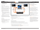
About the API
Connecting to the codec, cont...
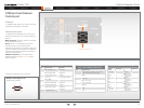
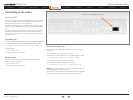
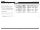
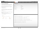
Hardware & Cabling (RS-232)
The pin outs for the RS-232 are defined in the tables to the right.
Observe that the DTE (Data Terminal Equipment), could be a PC or
any other device capable of serial communication.
Cable. A straight-through cable should be used between the
TANDBERG RS-232 port and the DTE. The lower table shows the
recommended cable-wiring scheme when connecting the TANDBERG
Codec C90 to a PC through RS-232.
DTR and RTS are ignored. DSR, CD, and CTS are always asserted,
while RI is not used.
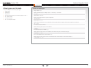
Troubleshooting (RS-232)
If communication cannot be established between the PC/terminal and
the TANDBERG Codec data port, the following should be checked:
Verify that the serial cable is a straight-through 9-pin to 9-pin 1.
cable.
Confirm that the configuration of the PC/terminal’s serial RS-232 2.
port is identical to the configuration of the TANDBERG RS-232
port.
Verify that the PC/terminal’s serial RS-232 port is working properly 3.
by connecting it back-to-back to another PC/terminal and send
characters in both directions.
COM port (RS-232)
Pin Signal name
Direction
1 Carrier detect, CD
From DCE
2 Receive data, RXD
From DCE
3 Transmit data, TXD
To DCE
4 Data terminal ready, DTR
From DCE
5 Signal GND
6 Data set ready, DSR
From DCE
7 Ready to send, RTS
To DCE
8 Clear to send, CTS
From DCE
9 Ring indicator, RI
From DCE
Cable wiring (RS-232) TANDBERG DCE <-> PC
TANDBERG DCE 9 pin Direction PC DTE, 9 pin
1 CD
—> 1 CD
2 RD
—> 2 RD
3 TD
<—
3 TD
4 DTR <—
4 DTR
5 GND <—> 5 GND
6 DSR —> 6 DSR
7 RTS <— 7 RTS
8 CTS —> 8 CTS
9 RI —> 9 RI