


D14128.02—NOVEMBER 2008
29
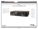
Codec C90
System Integrator Guide
Contents Introduction Getting Started Interfaces About the API xConfiguration xCommand xStatus Cameras Appendices Contact us
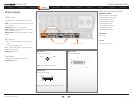
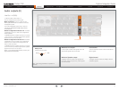
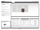
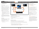
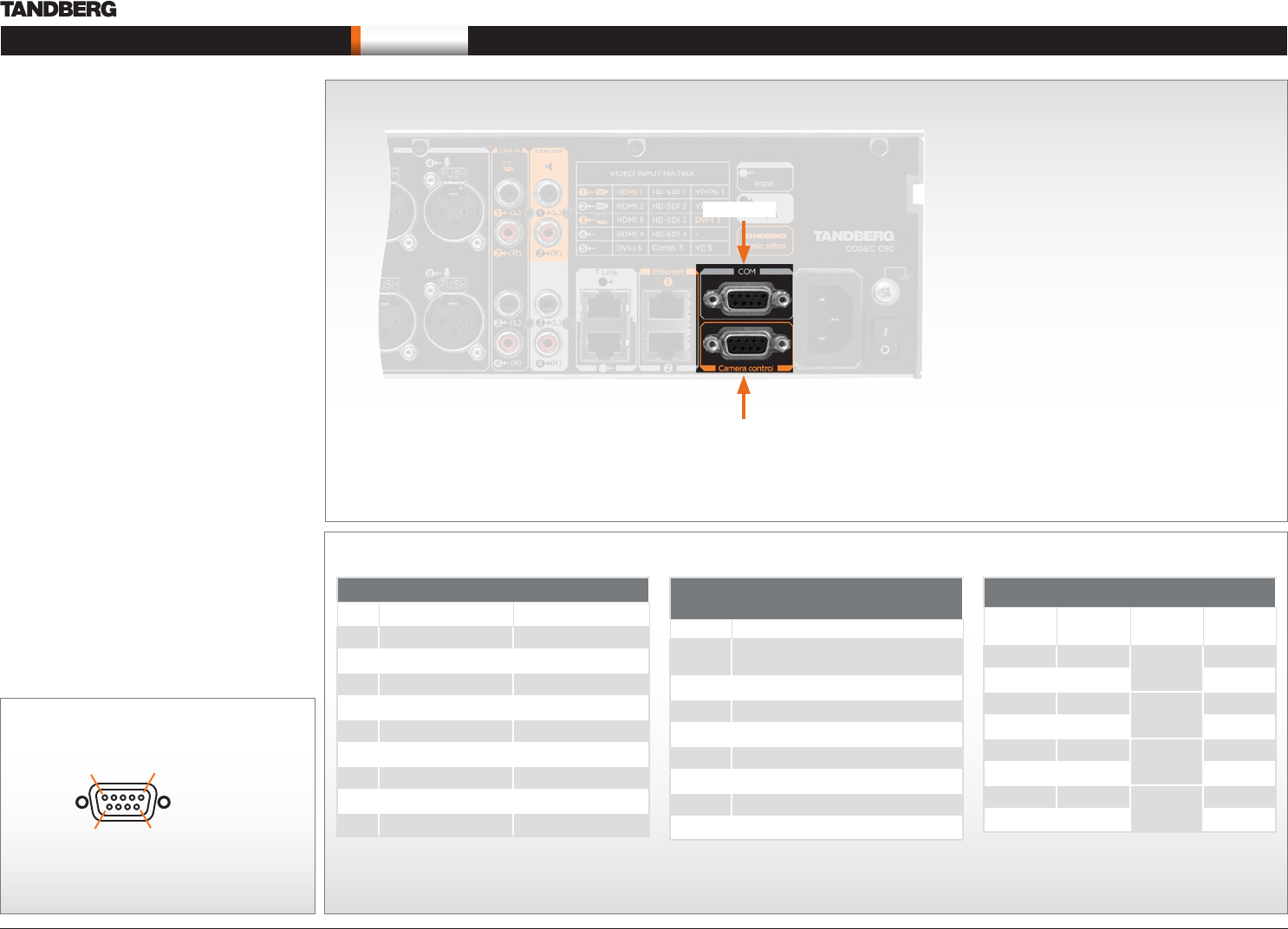
Interfaces
COM port and Camera
Control port
COM port
1 x COM (RS-232) data port for codec control and
configuration through API commands.
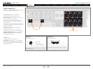
Camera Control port
1 x Camera Control (RS-232) port for power and
camera control (pan, tilt, zoom) using the VISCA™*
protocol.
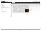
Main connector. The main camera is connected
to the Camera Control port.
Power. Pin No. 4 on the Camera Control port
provides 12 V DC / 1 A to the main camera.
If more than one camera is connected, only the first
camera is powered from the codec. The additional
cameras must be daisy chained by using a serial
cable and external power.
Additional cameras. For information about
additional cameras, go to the Cameras section
later in this guide.
*VISCA™ is a trademark of Sony Corporation
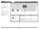
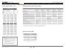
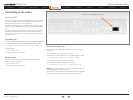
Pin-out—TANDBERG camera cable
Signal
name
RJ-45 pin D-SUB pin
+12V DC 1 Twisted
pair
4
GND 2 5
RX 3 Twisted
pair
2
TX 6 3
NC 4 Twisted
pair
1
NC 5 6
GND 7 Twisted
pair
5
+12V DC 8 4
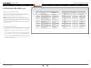
Pin-out—COM Port
Pin Signal name Direction
1
Carrier detect, CD From DCE
2
Receive data, RXD From DCE
3
Transmit data, TXD To DCE
4
12 V / 1 A To the main camera
5
Signal GND
6 Data set ready, DSR
From DCE
7 Ready to send, RTS
To DCE
8 Clear to send, CTS
From DCE
9 Ring indicator, RI
From DCE
Pin-out—VISCA™ camera control
RJ11, 8 pins shielded modular jack
Pin Signal name
8 +12V (presence 2.8mA current source
when connected in daisy chain)
7 GND
6 TXD (out)
5 NC (no connect)
4 NC (no connect)
3 RXD (in)
2 GND
1 +12V
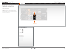
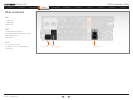
RS232 9 pin D-SUB pin-out
External view of socket
1 5
6 9
Camera Control Port
COM port