


SCPA033
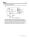
8 PCI1520 Implementation Guide
6 Miscellaneous Pin Interface
6.1 Multifunction Terminals
The multifunction terminals (MFUNC6:0) can be programmed to serve many different roles using
the Multifunction Routing register at PCI configuration offset 8Ch. The discrete ISA interrupts
(IRQ15:2), INTA#, INTB#, and IRQSER are explained in Section 7 – Interrupt Configurations.
CLKRUN#, D3STAT#, and RI_OUT# are discussed in Section 9 – Power Management
Considerations. ZVSTAT, ZVSEL1#, and ZVSEL0# are used for ZV control. For more
information, please refer to the PCI1520 Data Manual.
LED_SKT, LEDA1, and LEDA2 can be used to indicate socket activity. When a PC Card is
being accessed, these outputs will be driven high. LED_SKT will be driven high for access to
either socket. LEDA1 and LEDA2 will only be driven high during access to their respective
socket.
GPE#, GPIx, and GPOx can be used to signal general purpose events to the system.
CAUDPWM provides a PWM output for the CAUDIO terminals (as opposed to the binary output
SPKROUT).
PCI LOCK# is an optional PCI signal as mentioned in Section 4 – PCI Bus Interface.
All unused multifunction terminals require a 43kΩ pullup resistor.
6.2 SPKROUT
SPKROUT is the output to the host system that can carry SPKR# or CAUDIO through the
PCI1520 from the PC Card interface. If SPKROUT is enabled for both sockets, it is driven as an
exclusive-OR of the two inputs. A 43k pulldown resistor is required to prevent oscillation when
SPKROUT is disabled and therefore tristated.
6.3 SUSPEND#
The assertion of SUSPEND# gates PRST#, GRST#, and PCLK from the PCI1520. More
information can be found in Section 9 – Power Management Considerations. A 43kΩ pullup
resistor is required on SUSPEND#. SUSPEND# cannot be low during boot.