12
G8000 Series Installation and Operation Manual
7) The UPS generates and can radiate radio-frequency energy during operation. Although
RFI noise lters are installed inside of the unit, there is no guarantee that the UPS will
not inuence some sensitive devices that are operating near by. If such interference
is experienced, the UPS should be installed further away from the affected equipment
and/or powered from a different source than that of the installed equipment.
8) The user should provide over-current protection for hardwired UPS systems between
the UPS output and the load input.
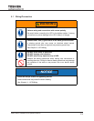
9) After ensuring that all power sources are turned “OFF” and isolated in accordance with
established lockout/tagout procedures, connect the power source wiring of the correct
voltage to the input terminals of the UPS.
NOTE: Ensure the input phasing is connected in clockwise rotation (CW). UPS internal
circuitry is designed to disable further UPS operation if the input phasing is
installed in counter-clockwise rotation (CCW).
10) Connect the output terminals of the UPS to the load (refer to NEC Article 300 - Wiring
Methods and Article 310 - Conductors For General Wiring). Size the branch circuit
conductors in accordance with NEC Table 310.16 as published 9/2007.
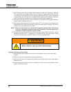
WARNING
METAL CONDUIT IS NOT AN ACCEPTABLE GROUND.
Conductor Routing and Grounding
1) Use separate metal conduits for routing the input power, output power, and control
circuits.
2) Follow the wire size and tightening torque specications.
3) Always ground the unit to reduce the potential for electrical shock and to help reduce
electrical noise.
4) A separate ground cable should be run inside the conduit with the input power, output
power, and control circuits.


