


41
G8000 Series Installation and Operation Manual
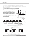
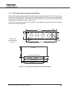
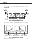
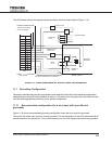
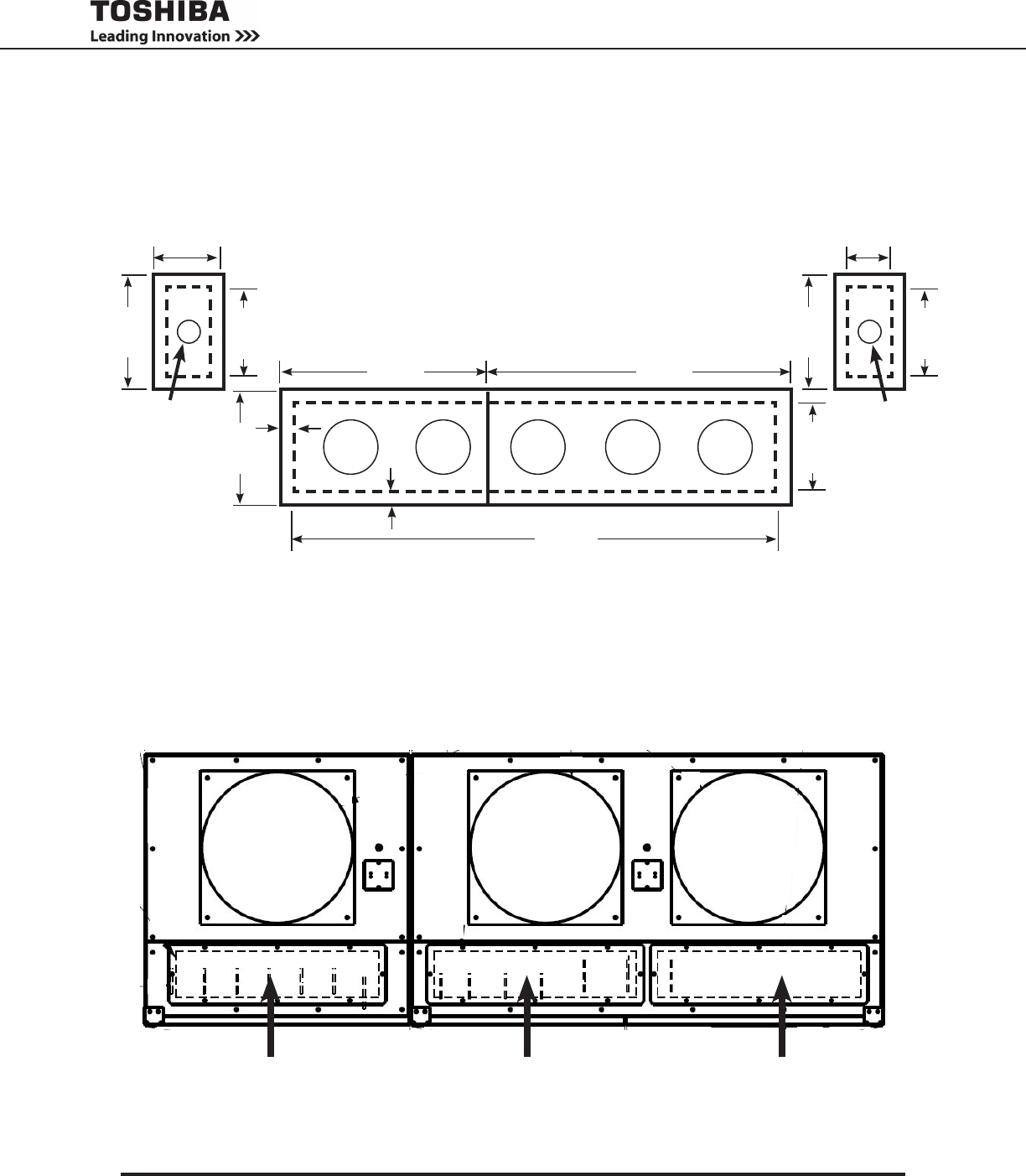
Figure 11.12 shows the four (4) cable landing plates provided at the top of the 300 kVA UPS. Seven (7)
holes must be punched during installation. The dashed rectangle indicates the UPS opening behind the
conduit landing plates.
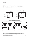
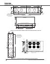
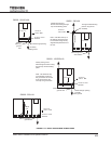
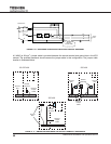
Figure 11.13 shows the three (3) conduit landing plates provided at the top of the 500 kVA UPS. The
dashed rectangle indicates the UPS opening behind the conduit landing plates.
Ensure that your installation adheres to local and NEC electrical codes.
FIGURE 11.13 - TOP CONDUIT LANDING PLATES FOR THE 500 KVA UPS
CABLE ENTRY PLATE
(AC INPUT, BYPASS INPUT)
28.0” X 6.3” (711 MM X 161 MM)
CABLE ENTRY PLATE
AC OUTPUT, DC INPUT
28.0” X 6.3” (711 MM X 161 MM)
CABLE ENTRY PLATE
(CONTROL)
28.0” X 6.3” (711 MM X 161 MM)
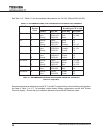
Recommended
Conduit Placement
Order in Top Conduit
Landing Plates
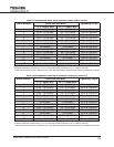
CONDUIT LANDING PLATES - DIMENSIONS
0.76 in.
0.76 in.
56.70 in.
7.09 in.
AC
INPUT
BYPASS
AC OUT-
PUT
BATTERY
37.4 in.21.26 in.
8.66 in.
BATTERY
CONTROL
WIRES
7.09 in.
3.15 in.
8.66 in.
GROUND
WIRE
7.09 in.
3.93 in.
8.66 in.
FIGURE 11.12 - TOP ACCESS CONDUIT LANDING PLATES (300 KVA)