


35
G8000 Series Installation and Operation Manual
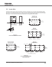
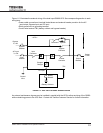
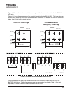
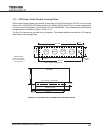
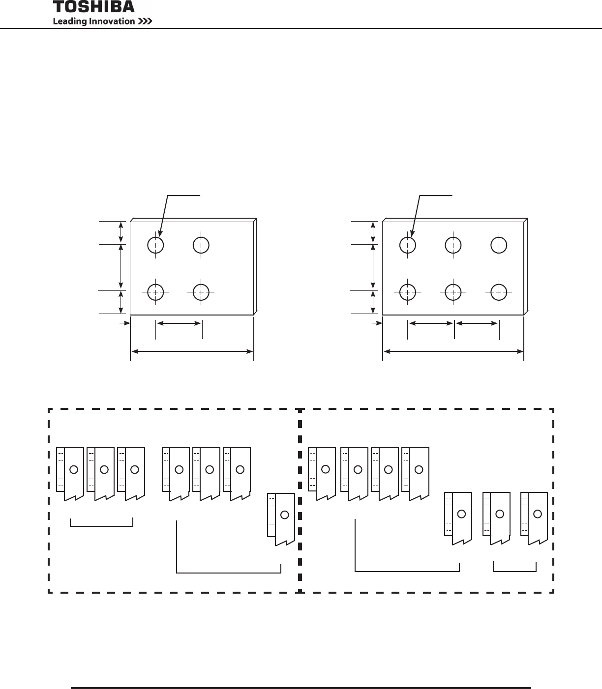
Figure 11.7 shows the terminal mounting hole arrangement for the terminal buss strips for the 500 kVA
UPS units.
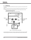
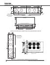
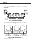
Figure 11.8 shows the arrangement of the terminal buss strips for the 500 kVA UPS. The buss strips are
located inside at the top of the unit. The dashed line on terminals 1–13 indicates the side view of the bolt
holes. Use 1/2 inch bolts to attach the lugs.
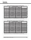
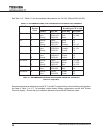
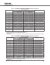
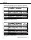
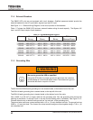
For UPS’ equipped with buss strip terminals for the A/C INPUT, BYPASS INPUT, A/C OUTPUT and
BATTERY connections, Toshiba recommends using the compression lugs listed in Table 11.3, or their
equivalent, for cable terminations to be mounted on the bus strips.
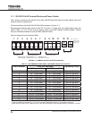
3-Phase AC Power Lugs
4 in. (102 mm)
1.75 in.
(44.5 mm)
0.875 in.
(22 mm)
1.75 in.
(44.5 mm)
6 x 0.5625 in. Dia.
(14.3 mm)
0.875 in.
(22 mm)
0.75 in.
(19 mm)
5.5 in. (140 mm)
1.75 in.
(44.5 mm)
1.75 in.
(44.5 mm)
0.875 in.
(22 mm)
1.75 in.
(44.5 mm)
6 x 0.5625 in. Dia.
(14.3 mm)
0.875 in.
(22 mm)
0.75 in.
(19 mm)
3-Phase Neutral and
Battery (DC) Power Lugs
FIGURE 11.7 - TERMINAL BUSS DETAILS FOR 500KVA UPS
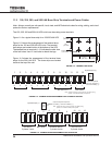
FIGURE 11.8 - TERMINAL BUSS ARRANGEMENT FOR 500 KVA UPS
G8000 500KVA - INPUT SECTION G8000 500KVA - OUTPUT SECTION
AC INPUT
U
1 2
V
3
W
BYPASS INPUT
7
N
U
4 5
V
6
W
BATTERY
13
–
14
+
U
9 10
V
11
W
12
N
AC OUTPUT
GND
8