


43
G8000 Series Installation and Operation Manual
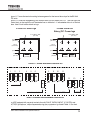
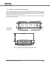
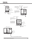
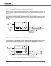
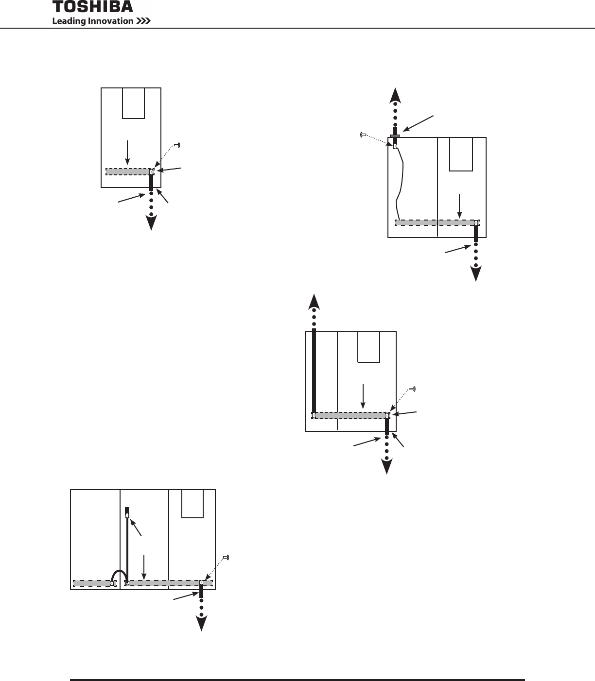
FIGURE 11.14 - EARTH GROUND WIRE CONNECTIONS
G8000 - 80/100 kVA
12 mm or 1/2 in.
Terminal
10 mm or
7/16 in. Bolt
Feed-through opening
AWG 2
(38 mm
2
)
ground
wire
To facility
earth ground
Groundbus
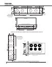
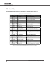
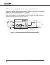
G8000 - 300 kVA
Through conduit landing
plate on top (recom-
mended)
Alternate ground
wire location
Note: Use either the top or
the bottom grounding point,
but not both. Doing so may
degrade the performance of
the unit.
10 mm or
7/16 in. Bolt
Facility earth ground.
Ground wire routing through
top conduit landing plate.
Groundbus
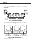
G8000 - 150/225 kVA
Groundbus
12 mm or 1/2 in.
Terminal
10 mm or
7/16 in. Bolt
Feed-through opening
AWG 2 (38 mm
2
)
ground wire
To facility
earth ground
Facility earth ground.
Alternate ground wire routing
through top conduit landing
plate.
Note: Use either the top
or the bottom access for
the ground wire to connect
to the ground buss, but
use only one ground wire.
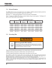
G8000 - 500 kVA
AWG 1/0 (50 mm
2
)
ground wire
12 mm or 1/2 in.
Terminal
10 mm or
7/16 in. Bolt
Ground
bus