G7 ASD Multi-Protocol Communication Option and PG Feedback Option Manual
6
Install the #51326A connector PCB in the control board's 80-pin connector, making sure that the
connector is fully seated. Next, position the option card and snap the connectors together. Finally,
secure the card to the standoffs with the remaining pan head screws (see Figure 2).
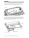
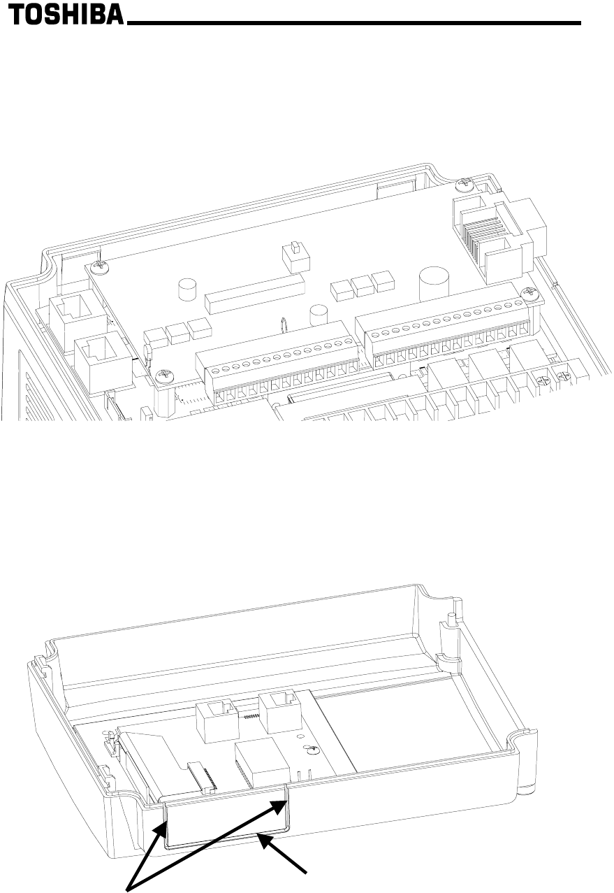
If your option card is equipped with a data connector along its right side edge, you will need to remove
the side access window of your drive's cover before reinstalling it. Place the cover upside down on a
level surface (see Figure 3), and with downward pressure on your utility knife, cut along the two vertical
grooves. Next, bend the resulting flap back and forth several times until it snaps apart. Clean up the
opening as necessary and reattach the front cover to the drive.
Figure 2
Cut these two edges
Bend and break apart
Figure 3


