G7 ASD Multi-Protocol Communication Option and PG Feedback Option Manual
26
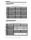
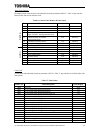
• Status Word (Offsets 2 and 3)
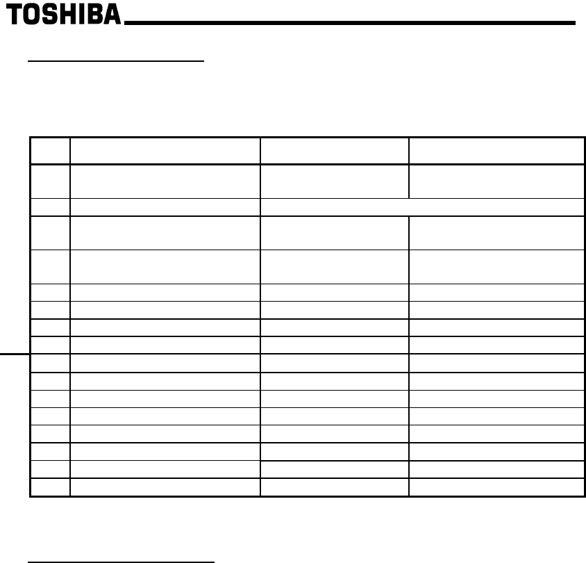
Bit-mapped status word. Table 14 provides the format of this status word.
Table 14 : Status Word Format
Bit Function 0 1
15 Ready for operation status
(not including MOFF)
Not ready Ready
14 Drive healthy signal Alternating heartbeat: “0” for 1s, then “1” for 1s
13 Ready for operation status (not
including ST)
Not ready Ready
12 Ready for operation status
(including ST)
Not ready Ready
11 Control mode status Speed control Torque / position control
10 Speed limit status Normal Speed limiting
9 Forward / reverse status Forward Reverse
High Byte
8 Jog status Normal Jogging
7 DC injection braking Normal DC injection braking active
6 OL alarm status Normal OL alarm
5 PI control status Normal PI control inactive
4 Alarm status No alarm Alarm
3 Serious fault status Normal Serious fault
2 Run / stop status Stopped Running
1 Alarm stop status None Alarm stopped
Low Byte
0 Fault status None Faulted
• Operating Speed (Offsets 4 ∼
∼∼
∼ 7)
Obtained from drive parameter 0xFE58. Continuously reports the drive’s operating speed. In order to
determine the drive’s actual output speed, the data contained in the output speed must first be converted
from hexadecimal to decimal, and then divided by 100. For example, if offset #6 is 0x12 and offset #7
is 0x34, then 0x1234 converted to decimal is 4660. Dividing this number by 100, the actual operating
speed of 46.60Hz is obtained.


