G7 ASD Multi-Protocol Communication Option and PG Feedback Option Manual
25
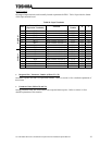
• Action Bits / Parameter Number (Offsets 32 ∼
∼∼
∼ 35)
Parameter action bits and 16-bit parameter number. Refer to section 9.6 for a detailed explanation of
these items.
• Parameter Data (Offsets 38 and 39)
During parameter writes, this contains the data to write. Refer to section 9.6 for a detailed explanation
of this location.
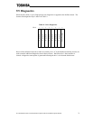
9.4.2 Input (Status) Data Format
The size of the input data structure from the Multicom interface to the network master is modular and
selectable from 4 to 40 bytes. The allocation of the maximum 40 bytes of the data structure is
comprised of 1 fixed four-byte status, 1 fixed four-byte output speed reference, 6 configurable four-byte
scan data selections (selectable via drive parameters F841-F846), and 1 eight-byte structure for
asynchronous parameter accesses. Refer to Table 13 for details.
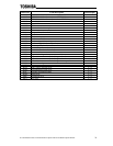
Table 13: Input (Status) data
Offset Data Offset Data
0 Reserved 20 Parameter F844 setting high byte
1 Reserved 21 :
2 Status high byte 22 :
3 Status low byte 23 Parameter F844 setting low byte
4 Operating speed high byte 24 Parameter F845 setting high byte
5 : 25 :
6 : 26 :
7 Operating speed low byte 27 Parameter F845 setting low byte
8 Parameter F841 setting high byte 28 Parameter F846 setting high byte
9 : 29 :
10 : 30 :
11 Parameter F841 setting low byte 31 Parameter F846 setting low byte
12 Parameter F842 setting high byte 32 Response bits / Reserved
13 : 33 Reserved
14 : 34 Parameter number response high byte
15 Parameter F842 setting low byte 35 Parameter number response low byte
16 Parameter F843 setting high byte 36 Reserved
17 : 37 Reserved
18 : 38 Parameter data response high byte
19 Parameter F843 setting low byte 39 Parameter data response low byte
Locations marked “Reserved” in the above table are reserved for future use. Presently, all “Reserved”
input data is set to 0 by the drive. Future releases of the drive firmware, however, may use these
locations for data transfer.


