


G7 ASD Multi-Protocol Communication Option and PG Feedback Option Manual
57
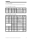
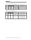
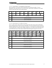
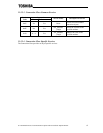
11.5.4.5.5 Input Instance 71 (Extended Speed Control Input)
This is the ODVA AC/DC Drive Profile Extended Speed Control Input assembly. For more
information, refer to the
ODVA DeviceNet Specifications
and the object explanations in this manual
related to each of the fields of this assembly instance.
Byte # Bit 7 Bit 6 Bit 5 Bit 4 Bit 3 Bit 2 Bit 1 Bit 0
0
At
Reference
Ref From
Net
Ctrl From
Net
Ready
Running2
(REV)
Running1
(FWD)
Warning Faulted
1
Drive State
2
Speed Actual (Low Byte)
3
Speed Actual (High Byte)
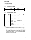
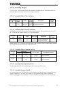
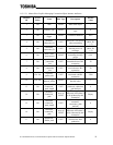
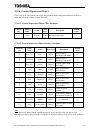
11.5.4.5.6 Input Instance 150 (Toshiba ASD Status)
This is a vendor-specific input assembly instance that provides direct access to the most often-used
status components of the G7 ASD. For more information, refer to the explanations for the referenced
attributes contained in the AC/DC Drive Object in section 11.5.8.6 on page 69. Note that bytes #0 and
#1 are mapped to the “G7 Status Word” attribute (attribute ID #111) of the AC/DC Drive Object: the
specific bits of this status word are shown in detail in the following table simply for ease of use.
Byte # Bit 7 Bit 6 Bit 5 Bit 4 Bit 3 Bit 2 Bit 1 Bit 0
0
DC Inject.
Braking
OL Alarm
Status
PI Status
Alarm
Status
Serious
Fault
Run / Stop
Status
Alarm Stop
Status
Fault Status
1
Ready (exc.
MOFF)
Drive
Healthy
Ready (exc.
ST)
Ready (inc.
ST)
Control
Mode
Speed Limit
FWD /
REV Status
Jog Status
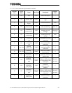
2
Output Frequency (Low Byte)
3
Output Frequency (High Byte)
4
F841 Status Data (Low Byte)
5
F841 Status Data (High Byte)
6
F842 Status Data (Low Byte)
7
F842 Status Data (High Byte)