G7 ASD Multi-Protocol Communication Option and PG Feedback Option Manual
36
10. RS-485 Interface
This section applies to ASD-MULTICOM-A option boards only.
10.1 Physical Layer
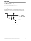
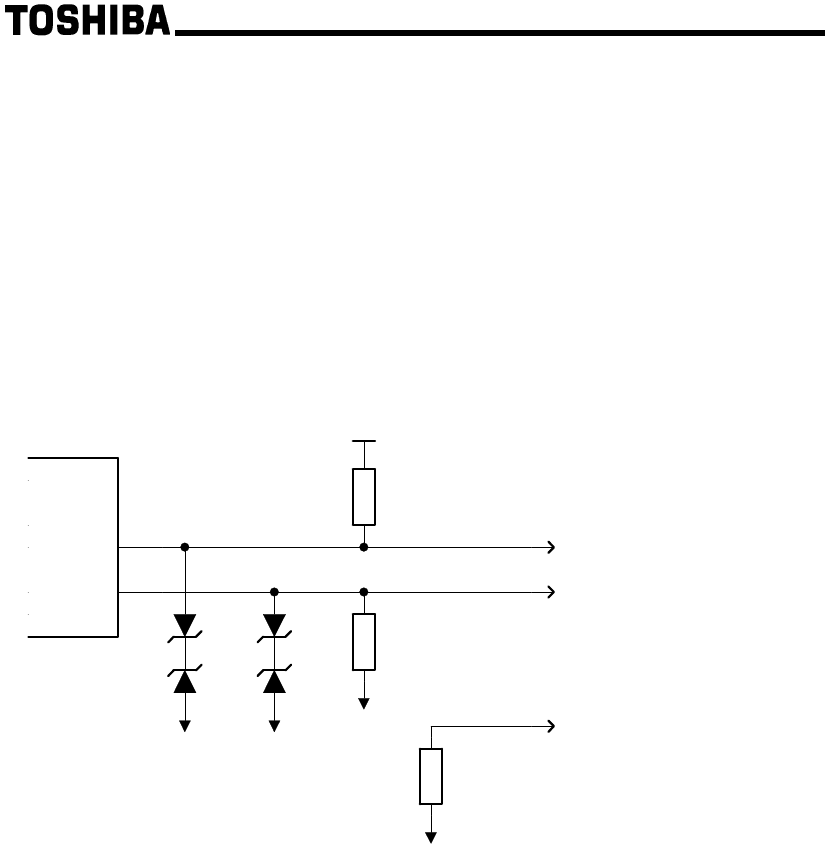
Figure 3 shows the physical layer for the RS-485 portion of the Multicom interface. This circuit
diagram is provided as an aid to the system (network) designer to ensure that externally-connected
circuitry will provide the required voltages etc. necessary for sufficient and robust communications.
ZD4
6.2V
TB1:9
GNDISO
GNDISO
47k
R38
ZD3
6.2V
P5ISO
TB1:11
TB1:10
47k
R37
ZD2
6.2V
GNDISO
RS-485
NETWORK
GNDISO
6.2V
ZD1
200
R26
B
A
Figure 3: RS-485 Physical Layer


