


Replacement Procedures
Satellite M300 and Satellite Pro M300 Maintenance Manual (960-Q08)
4-iii
Figures
Figure 4-1 Remove the battery pack.................................................................................... 4-8
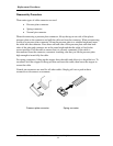
Figure 4-2-1Remove a PC card............................................................................................ 4-10
Figure 4-2-2 Insert a PC card............................................................................................... 4-11
Figure 4-3 Remove the HDD assembly............................................................................. 4-12
Figure 4-4 Remove a HDD................................................................................................ 4-14
Figure 4-5 Remove a wireless LAN card .......................................................................... 4-16
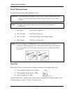
Figure 4-7 Remove a memory module .............................................................................. 4-21
Figure 4-8 Insert a memory module.................................................................................... 4-21
Figure 4-9 Remove screws for KBD cover/keyboard......................................................... 4-24
Figure 4-10 Remove the keyboard/KBD cover ................................................................... 4-24
Figure 4-11 Remove the keyboard……………………………………………………… 4-25
Figure 4-12/14 Remove an optical disk drive...................................................................... 4-26
Figure 4-15 Disassemble the side bracket ........................................................................... 4-29
Figure 4-16 Remove the screws………………………………………………… ………. 4-30
Figure 4-17 Disconnect the Cable........................................................................................ 4-31
Figure 4-18 Remove the Wireless LAN antenna connector ................................................ 4-33
Figure 4-19 Remove the screws (from bottom side) ........................................................... 4-34
Figure 4-20 Remove the Wireless Antenna and LCD cable................................................ 4-36
Figure 4-21 Remove the hinge screw…………………………………………………….. 4-36
Figure 4-22 Remove the LCD harness and remove display assembly…………………….4-37
Figure 4-23 Remove the touch board and touch pad plate screw………………………… 4-39
Figure 4-24 Remove the touch pad………………………………………………………...4-40
Figure 4-25 Remove the Lan board ..................................................................................... 4-42
Figure 4-26 Disconnect the battery cable ............................................................................ 4-43
Figure 4-26-1 Remove the system board............................................................................. 4-45
Figure 4-27 Remove the CPU heat sink .............................................................................. 4-46
Figure 4-28 Remove the CPU.............................................................................................. 4-47
Figure 4-29 Apply silicon grease......................................................................................... 4-48
Figure 4-30 Remove the display mask................................................................................. 4-50
Figure 4-31 Remove the FL inverter ................................................................................... 4-51