


4 Replacement Procedures
4-vi EQUIUM M40/M45 / Satellite M40/M45 Maintenance Manual
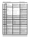
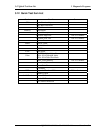
Figures
Figure 4-1 Removing the battery pack ................................................................................. 4-8
Figure 4-2 Removing the battery pack ................................................................................. 4-9
Figure 4-3 Removing the PC card ...................................................................................... 4-10
Figure 4-4 Removing the optional memory cover.............................................................. 4-12
Figure 4-5 Removing the optional memory........................................................................ 4-13
Figure 4-6 Removing the wireless LAN card cover............................................................ 4-15
Figure 4-7 Removing the MDC card .................................................................................. 4-16
Figure 4-8 Removing the wireless LAN card cover........................................................... 4-18
Figure 4-9 Removing the wireless LAN card..................................................................... 4-19
Figure 4-10 Removing the HDD pack cover ...................................................................... 4-20
Figure 4-11 Removing the HDD pack ............................................................................... 4-21
Figure 4-12 Removing the HDD chassis ............................................................................ 4-21
Figure 4-13 Removing the CPU cover................................................................................ 4-23
Figure 4-14 Removing the Coolling module ...................................................................... 4-24
Figure 4-15 Applying silicon greases ................................................................................. 4-24
Figure 4-16 Removing the CPU ......................................................................................... 4-26
Figure 4-17 Installing the CPU........................................................................................... 4-27
Figure 4-18 Fix the CPU..................................................................................................... 4-28
Figure 4-19 Removing the speaker cover........................................................................... 4-29
Figure 4-20 Removing the keyboard .................................................................................. 4-30
Figure 4-21 Removing the ODD bay module .................................................................... 4-31
Figure 4-22 Removing the ODD bay module..................................................................... 4-32
Figure 4-23 Removing the bracket from ODD drive.......................................................... 4-33
Figure 4-24 Removing the screws from the back of the computer..................................... 4-34
Figure 4-25 Removing the display assembly...................................................................... 4-35
Figure 4-26 Removing the screws from the bottom of the computer................................. 4-36
Figure 4-27 Removing the top cover .................................................................................. 4-37
Figure 4-28 Removing the system board............................................................................ 4-39
Figure 4-29 Removing the RJ11/45, AC-IN, MDC cable .................................................. 4-40