


Copyright 2008 Unitech Electronics Co., Ltd. All rights reserved. Unitech is a registered trademark of Unitech Electronics Co., Ltd.
44
Copyright 2008 Unitech Electronics Co., Ltd. All rights reserved. Unitech is a registered trademark of Unitech Electronics Co., Ltd.
45
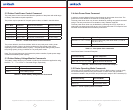
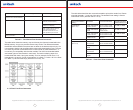
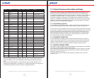
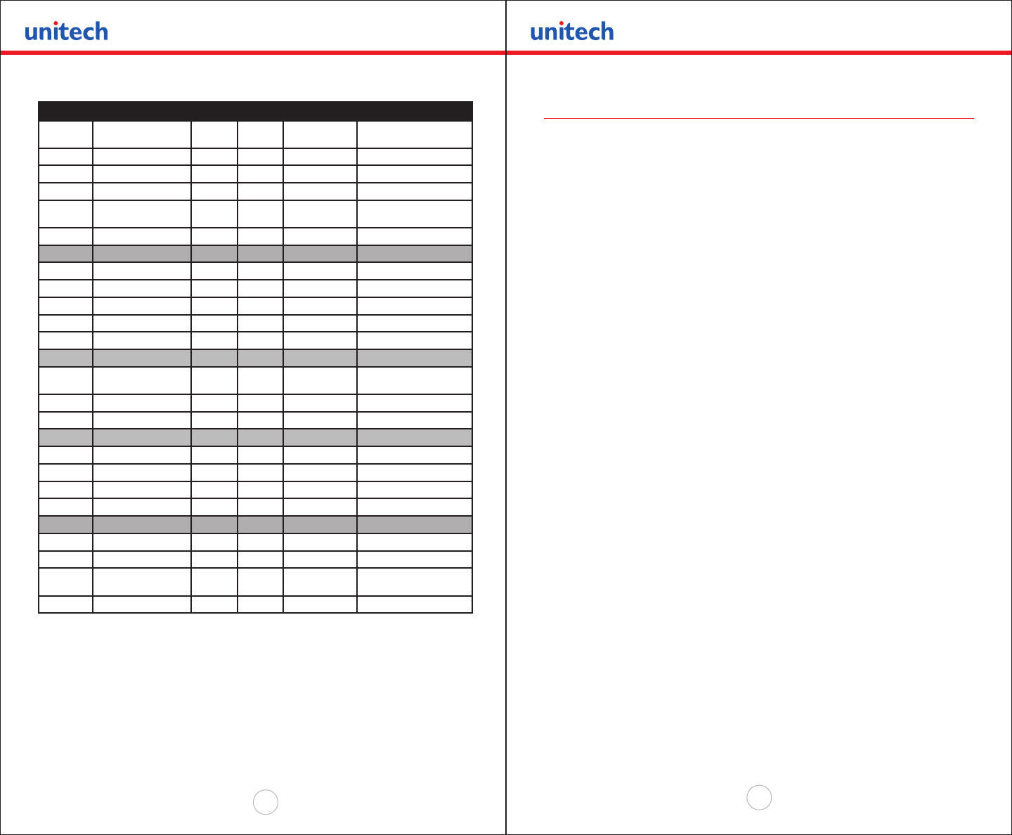
Switch # Function Switch Switch Switch NOTES:
1 & 5 Communication
Interface
SW1 SW5 SW7
RS232 Off Off SET SW 2,3,6 &7
RS232 and Bluetooth Off On Defaults to 38.4k Baud
IrDA Set to 9600 On Off Baud rate xed to 9600
IrDA Variable 9600-
38.4K
On On
Direct IR On Off On Defaults to 9600 Baud
2 & 3 Baud Rate SW2 SW3
38,400 Off Off (DEFAULT)
19,200 Off On
9,600 On Off
2,400 On On
4 Printer Power Timer
Control
SW4 Software control
Continuous Power On On
Auto Power Off Off (DEFAULT)
6 & 7 Parity bit SW6 SW7
No Parity Off Off (DEFAULT)
Odd Parity On Off
Even Parity On On
8 Printer-Power-Control SW8 Hardware control
Continuous Power ON
On Remove the battery to shut
down printer
Auto Power Off Off (DEFAULT)
Table C.0 - Dip Switches and their functions
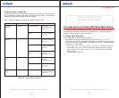
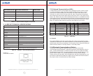
Note: The MP200 printer also supports direct IR printing. For direct IR to work you
need DIP switches 1 and 7 in the ON position and all other Dip switches need to be
OFF.
Please note that if Dip Switch # 1 is OFF then the function of Dip Switch # 7 is as
described in the table above. If Dip Switch # 1 is ON then Dip Switch # 7 being ON or
OFF determines whether we are in Direct IR or variable IrDA mode.
C.1.0 Serial Communication Rate and Parity
The RS232C Interface signals for the MP200 Series printers are terminated on a 6
PIN RJ type data connector located on the side of the printer. Six connections are
provided from the Serial Interface to the host computer. A minimum of two connections
is required for operation, RXD – pin 3 and Common – pin 1.The proper baud rate
and protocol settings are required to communicate with the host device. The printer
defaults to 19200 BAUD, 8 DATA BITS, NO PARITY BIT, and one STOP BIT on initial
power up. Two communication handshaking protocols are supported by the MP200,
Serial Busy protocol and XON/XOFF protocols.
C.1.1 Serial Busy Protocol
For the serial busy handshaking mode, request to send printer input (RTS) and clear
to send printer output (CTS) are used to control data ow to and from the printer.
The RTS and CTS are considered to be valid or active when the signal level is positive
(3 to 12VDC). A positive RTS signal from the host device enables the printer. The RTS
signal is monitored during data transmission from the printer to the host device, the
printer transmits data to the host device only if RTS input is high. The printer raises
CTS output when it is ready to accept data. The printer lowers CTS line when the
print buffer has less than 256 unused locations.
C.1.2 XON/XOFF PROTOCOL
For the XON/XOFF handshaking mode, the printer transmits XON (0x11) when it is
ready to accept data, and XOFF (0x13) for the print buffer has less than 256 unused
locations. Under XON/XOFF protocol, the data ow out of the printer’s serial port is
halted on receipt of XOFF from Host device and resumed on receipt of XON.
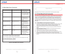
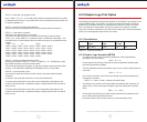
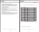
C.1.3 RS232C CONNECTIONS
The RS232C Interface signals for the Unitech MP200 are terminated on a 6 PIN RJ25
type data connector located at the back of the printer.
Six connections are provided from the Serial Interface to the host computer. The table
below lists the Serial Interface signals and pinouts on the RJ25 connector while pin
locations are shown in Figure 2.
A minimum of two signal connections are required for operation, RXD - pin3 and
Common - pin1.