Index
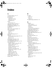
TM-XDOP-01XN IX–3
EXIT 1–6, 3–6
LCL/RMT 1–5, 3–6
MENU 1–6
OUT ON/OFF 1–5, 3–6
PROT SET 1–5, 3–6
RECALL 1–6, 3–6
STORE 1–5, 3–5
VOLTAGE 3–5
G
General Purpose Interface Bus. See GPIB.
GPIB
configuration 4–20
connection 4–19
electrical specifications E–4
location 4–3
mechanical specifications E–4
performance specifications E–4
protocol specifications E–3
using 4–21
GPIB control mode described 1–12
GPIB port 1–11
ground screw 1–11
I
identification 4–42
IEC viii, A–13
IEC symbols
Caution ix
Earth (Ground) Terminal ix
Off (supply) ix
On (supply) ix
Protective Conductor Terminal ix
Warning (Shock Hazard) ix
incorrect code B–3
information about your power supply 3–50, 4–42
Information about Your System form WA–4
input connector 2–7
input power 2–7
input wires
connecting 2–13
recommended size 2–8
specifications 2–8, 2–10, 2–12
installation
AC input power 2–7
connecting multiple loads 2–19
connecting single load 2–18
inspecting the power supply 2–2
load wiring 2–16
location 2–4
mounting 2–4
rack mounting 2–4
tests 2–13
ventilation requirements 2–6
Interlock display annunciator 1–10
inverter
purchase date WA–4
serial number WA–4
K
keypad, illustrated 1–3, 1–4, 1–5
KNOB LOCKOUT (menu item) 3–7, 3–44
L
LCL display annunciator 1–10
LCL/RMT key 1–5, 3–6
limits, changing setpoint 3–45
load connections
illustrated 2–19
wire size 2–18
load wiring
current carrying capacity 2–16
length 2–16
noise and impedance 2–17
local control mode, described 1–12
local lockout 4–26
local mode
changing 4–26
locking out voltage and current knobs 3–44
M
maintenance 2–3
Master display annunciator 1–10
menu
navigation 3–6
menu items
AUTO SEQ PGM 3–6
CALIBRATION 3–7
CURRENT SHARE 3–6
DISPLAY CFG 3–7
ERROR MSGS 3–6
KNOB LOCKOUT 3–7
TM-XDOP-01XN.book Page 3 Monday, July 17, 2006 11:19 AM


