


XEROX DOCUPRINT 96/DOCUPRINT 96MX LPS INSTALLATION PLANNING GUIDE 3-1
3. 3Preinstallation
This chapter assists you in preparing for the installation of your
DocuPrint 96/DocuPrint 96MX Laser Printing System (LPS). Consult
your customer support representative for the requirements of any
optional equipment or communications devices that may have been
ordered. For example, the peripheral cabinet and bypass transport
options have space requirements, and Ethernet requires that you
establish an Ethernet address. Refer to the “LPS options” chapter of
this guide for further information.
Keep in mind that preparing for your LPS installation is a
responsibility shared by both your site and your Xerox or Xerox
Limited representatives. Your representatives are available to
discuss installation issues and to assist you in completing the site
installation responsibilities as follows:
• LPS space and delivery requirements
• Environmental and electrical requirements
• Cabling requirements
• Supply requirements
If you have purchased additional equipment for use with your
DocuPrint 96/DocuPrint 96MX LPS, such as finishers or feeders,
from a company other than Xerox, it is important to remember to work
with the representatives of the company when planning the
installation. Space planning, electrical and environmental
requirements, and so forth, are important considerations to
remember.
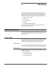
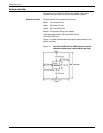
LPS delivery requirements
Dimensions and weights of the DocuPrint 96/DocuPrint 96MX LPS
system controller and printer are listed in this chapter, along with
diagrams to help you visualize the sizes and total space
requirements.
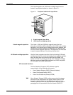
Note: For information on sharing space and other space planning
considerations, refer to the “Space planning guidelines” section of
this chapter. Space planning templates, a space planning template
transparency, and a grid are also provided at the end of this chapter
to assist you in planning the placement of your DocuPrint 96/
DocuPrint 96MX LPS. Contact your service representative if you
have questions not specifically addressed in this guide.
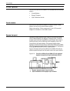
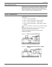
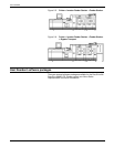
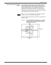
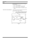
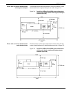
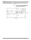
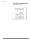
The following diagrams represent top views of the components,
surrounded by the required minimum clearance on all sides.