


PREINSTALLATION
3-12 XEROX DOCUPRINT 96/DOCUPRINT 96MX LPS INSTALLATION PLANNING GUIDE
Efficiency of use
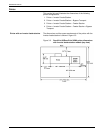
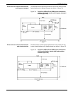
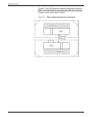
There are many possible layouts for your LPS. Placement depends
on the type and amount of equipment used and the size and shape
of the room used to house the equipment. Some possible
configurations for LPS components include:
• Side by side
• L-shaped
• Face to face.
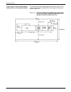
Equipment placement should limit operator movements as much as
possible. Here are a few suggestions that may be helpful:
• Place the system controller as close to the output end of the
printer as possible. This will enable operators to simply reach
over to collect printed materials and check output.
• Consider the location of supplies in relation to the placement of
the equipment. For example, having paper as close to the
printer as possible will save time.
• Having the system controller as close as possible to any offline
interface devices saves time when monitoring tapes, jobs, and
so forth.
Delivery access requirements
It is easy to overlook how the equipment is going to get from the truck
to the operation site. Does it need to go up stairs? Do you have an
elevator if it is to be located above the first floor? Is the elevator large
enough? How wide are the hallways? The doorways? Do you have a
loading dock or a specific door to which the equipment should be
delivered?
All these issues need to be reviewed prior to or at the time of the site
inspection that is done by your service representative.
The equipment dimensions are specified earlier in this chapter, so it
is easy to know whether or not your hallways and doorways are wide
enough to permit travel through them.
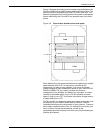
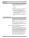
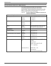
Turning radius The width of the passageway when the equipment must negotiate a
corner, whether into a room (or elevator) or into another
passageway, must also be considered.
The DocuPrint 96/DocuPrint 96MX is delivered with the printer and
the inverter feeder/stacker as two separate modules. If necessary,
the printer can be separated into two pieces for easier moving. The
larger of the two parts contains the xerographic system; the smaller
of the parts (referred to here as the PHM) contains paper trays 1 and
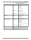
2. Table 3-1 describes the turning requirements for the printer when
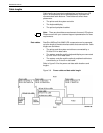
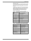
attached to the PHM (not separated). Table 3-2 describes
requirements for the printer without the PHM (separated). Do not
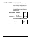
confuse these two parts of the printer with the inverter and feeder/
stacker modules, which have their own turning requirements.
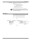
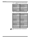
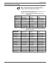
Table 3-3 describes the turning requirements for the printer if it is
upended for easier moving or stair-climbing. This table reflects
requirements for the printer separated from the PHM.