SP601 Hardware User Guide www.xilinx.com 35
UG518 (v1.1) August 19, 2009
Detailed Description
13. User I/O
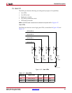
The SP601 provides the following user and general purpose I/O capabilities:
• User LEDs
• User DIP switch
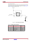
• Pushbutton switches
• CPU Reset pushbutton switch
• GPIO male pin header
Note:
All GPIO location constraints are collected in one partial UCF in Figure 1-27.
User LEDs
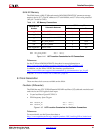
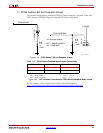
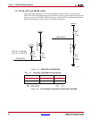
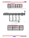
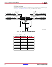
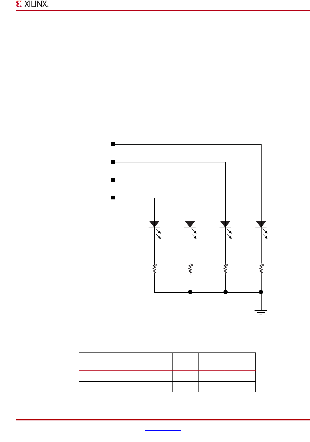
The SP601 provides four active high, green LEDs, as described in Figure 1-23 and
Table 1-17.
X-Ref Target - Figure 1-23
Figure 1-23: User LEDs
Table 1-17: User LEDs
Reference
Designator
Signal Name Color Label FPGA Pin
DS11 GPIO_LED_0 Green
E13
DS12 GPIO_LED_1 Green C14
R94
27.4
1%
1/16W
1
2
LED-GRN-SMT
2
DS14
1
UG518_23_070809
R93
27.4
1%
1/16W
1
2
LED-GRN-SMT
2
DS13
1
R92
27.4
1%
1/16W
1
2
LED-GRN-SMT
2
DS12
1
R91
27.4
1%
1/16W
1
2
LED-GRN-SMT
2
DS11
1
GPIO LED 3
GPIO LED 2
GPIO LED 1
GPIO LED 0


