SP601 Hardware User Guide www.xilinx.com 41
UG518 (v1.1) August 19, 2009
Power Management
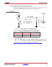
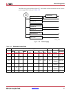
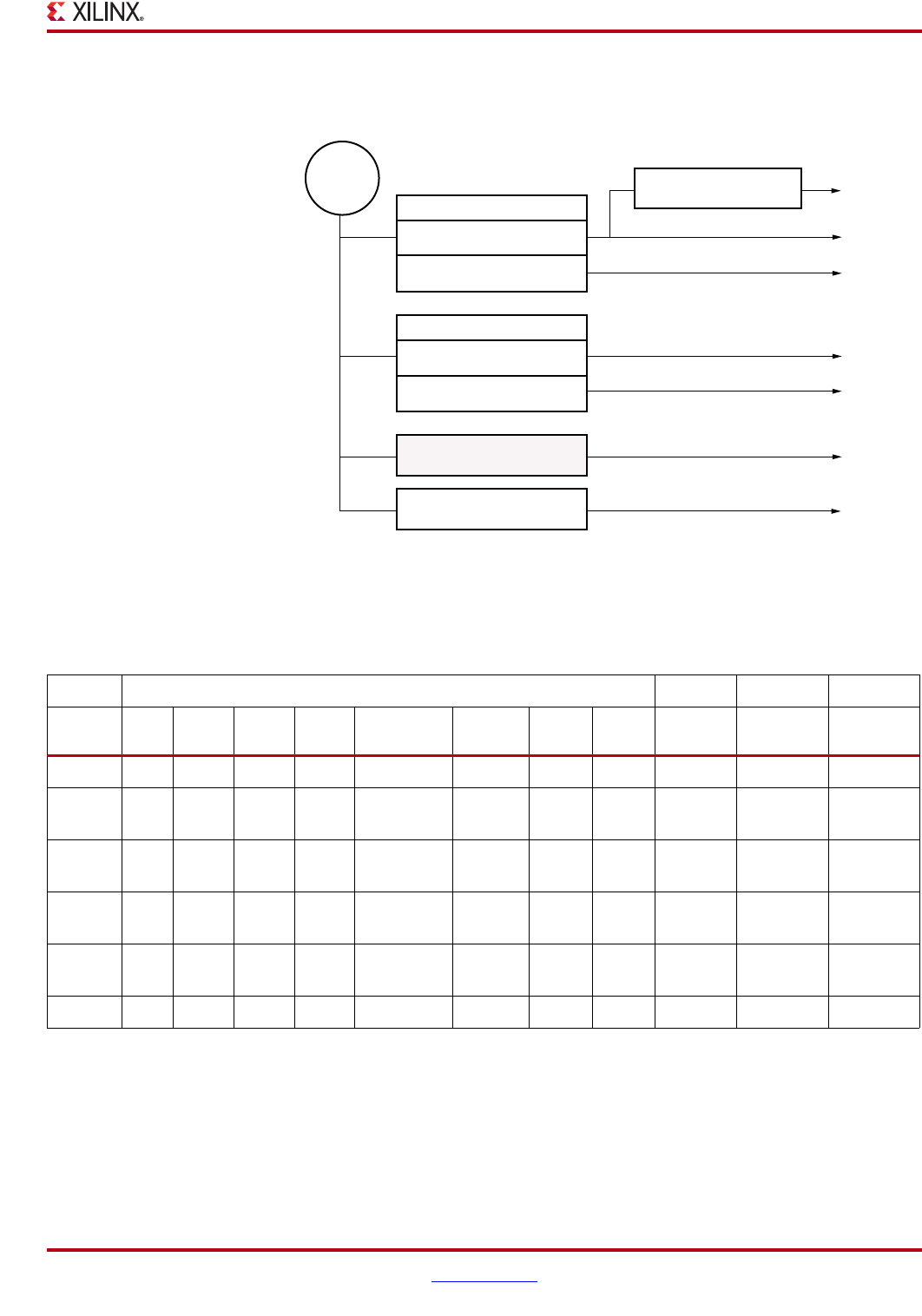
The SP601 uses power solutions from LTC. An estimate of the current draw on the various
power supply rails is shown in Table 1-22.
X-Ref Target - Figure 1-30
Figure 1-30: Power Supply
5V
PWR
Jack
Dual Switcher LTM4616
3. 3V@8A max
2. 5V@8A max
Dual Switcher LTM4616
1. 2V@8A max
1. 8V@8A max
Linear Regulator LT1763
Monolithic Regulator
0.9V@3A max
Buck-Boost Regulator LT1731
12V@1A max
3. 0V@500mA max
UG518_30 _070809
Table 1-22: Estimated Current Draw
Rail (V) Estimated Current (A)
FMC
LX16
Int/Aux
LX16
V
CCO
DDR2
BPI/SPI
Flash
USB
CP2103
Clock
Socket
Marvell
EPHY
Estimated
Totals
LTC
µModule
Comments
12 1.0 1.0 LT1731 12V, 3A
3.3 3.0 2.0 0.3 0.1 0.1 5.5
(1/2)
LTM4616
3.3V, 8A
2.5 0.1 1.0 1.1
(1/2)
LTM4616
2.5V, 8A
1.8 1.0 1.3
(1/2)
LTM4616
1.8V, 8A
1.2 3.0 2.0 5.0
(1/2)
LTM4616
1.2V, 8A
V
TT
0.9 1.0 1.0 LTC3413 0.9V, 1.0A


