40 www.xilinx.com SP601 Hardware User Guide
UG518 (v1.1) August 19, 2009
Chapter 1: SP601 Evaluation Board
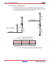
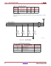
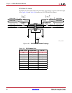
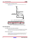
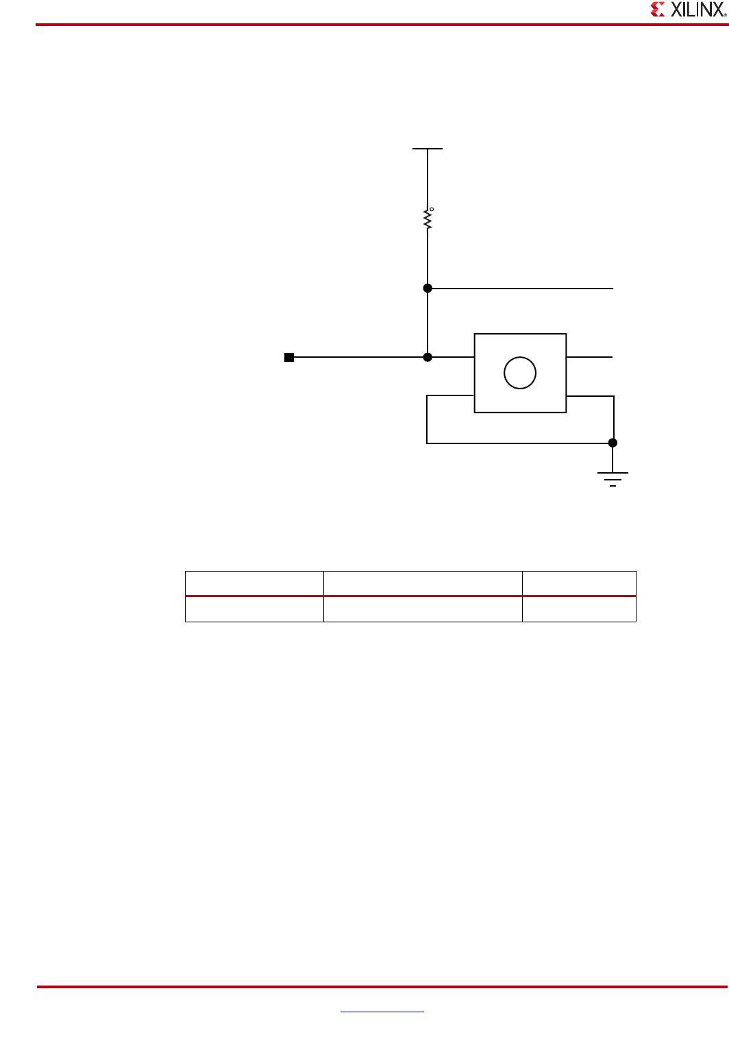
14. FPGA_PROG_B Pushbutton Switch
The SP601 provides one dedicated, active low FPGA_PROG_B pushbutton switch, as
shown in Figure 1-28.
Power Management
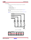
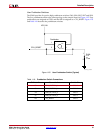
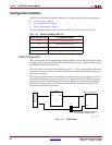
AC Adapter and 5V Input Power Jack/Switch
The SP601 is powered from a 5V source that is connected through a 2.1mm x 5.5mm type
plug (center positive).
SP601 power can be turned on or off through a board mounted slide
switch. When the switch is in the on position, a green LED (DS15) is illuminated.
Onboard Power Supplies
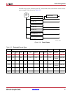
The diagram in Figure 1-30 shows the power supply architecture and maximum current
handling on each supply. The typical operating currents are significantly below the
maximum capable. The board is normally shipped with a 15W power supply, which
should be sufficient for most applications.
X-Ref Target - Figure 1-28
Figure 1-28: FPGA_PROG_B Pushbutton Switch Topology
Table 1-21: FPGA_PROG_B Pushbutton Switch Connections
FPGA U1 Pin Schematic Netname SW3 Pin
V2 FPGA_PROG_B 1
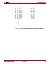
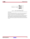
X-Ref Target - Figure 1-29
NET "FPGA_PROG_B" LOC = "V2";
Figure 1-29: UCF Location Constraints for BPI Flash Connections
VCC2V5
FPGA PROG B
Pushbutton
R24
4.7K
5%
1/16W
1
2
1
P1
P2
P4
P3
2
4
3
SW3
UG518_28_070809


