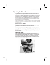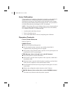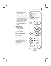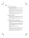
AC Power ON/OFF Switch
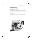
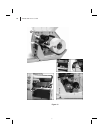
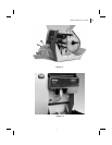
This switch is located on the left side of the printer near the AC power cord
and fuse (see Figure 6). The AC power switch should be turned off before
connecting or disconnecting any cables.
Turning the switch on activates the printer and causes it to perform a Power
ON Self Test, which can take up to 30 seconds, as it begins operation.
Turning the printer power on while holding down certain front panel keys
will activate additional printer self tests following the Power ON Self Test.
See Troubleshooting.
External influences, such as lightning storms or unwanted noise on the
power or data cables, may cause erratic printer behavior. Turning the AC
power off and back on may re-establish proper printer operation.
Otherwise, see Troubleshooting.
Printing a Test Label
Before you connect the printer to your computer, make sure that the printer
is in proper working order. You can do this by printing a configuration
label (refer to the “CANCEL Key Self Test” in Troubleshooting.) If you
can’t get this label to print, refer to Troubleshooting.
To make print quality adjustments, refer to “Print Quality Adjustments” in
Routine Care and Adjustments.
Connecting the Printer and Computer
This printer comes with both a nine-pin Electronics Industries Association
(EIA) RS-232 serial data interface and an IEEE 1284 bi-directional parallel
data interface. In either case, you must supply the required interface cable
for your application.
CAUTION: This printer complies with FCC “Rules and Regulations,”
Part 15, for Class B Equipment, using fully shielded six-foot data cables.
Use of longer cables or unshielded cables may increase radiated emis-
sions above the Class B limits.
RS-232 Interface Requirements
Refer to Figure 6.
The required cable must have a 9-pin “D” type (DB-9P) connector (male)
on one end, which is plugged into the mating (DB-9S) connector (female)
located inside the access opening on the left side of the printer.
The other end of the signal interface cable connects to a serial port at the
host computer. This cable will be one of two types -- standard or null
modem -- depending on the specific interface requirements.
18 S400 & S600 User’s Guide
26


