


AES-100 User’s Guide
2-2 Hardware Overview
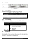
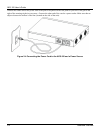
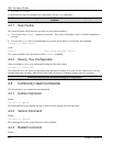
Figure 2-1 AES-100 Front Panel
2.3.1 Front Panel Ports
The following table describes the ports on the front panel of an AES-100 network module.
Table 2-1 Front Panel Ports of an ADSL Network Module
PORTS DESCRIPTION
LAN The LAN port is a 10/100 Mbps auto-sensing Ethernet port for connection to a
router.
CONSOLE The CONSOLE port is an RS-232 port for configuring the AES-100.
USER 1-8 The USER port connects to the user (subscriber) ADSL equipment.
CO 1-8 The CO port connects to the central office or a PBX.
2.3.2 Front Panel LEDs
The following table describes the LED indicators on the front panel of an AES-100 network module.
Table 2-2 AES-100 Network Module LED Descriptions
LED COLOR STATUS MEANING
ALM Red On The AES-100 network module has overheated.
LINK Green On
Off
The LAN port link is up.
The LAN port link is down.
SYS Green On
Off
Blinking
Your AES-100 Network Module is on and functioning properly.
The system is not ready or has a malfunction.
The system is initializing.
ACT Green Off
Blinking
The LAN port is not active.
Data is being sent.
ADSL 1-8 Green On
Off
The ADSL link is up.
The ADSL link is down.
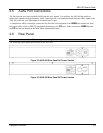
2.4 Console Port
For the initial configuration, you need to use terminal emulator software on a computer and connect it to the AES-
100 through the console port. Connect the male 9-pin end of the console cable to the console port of the AES-100.
Connect the other end (either a female 25-pin or female 9-pin) to a serial port (COM1, COM2 or other COM port)
of your computer. You can use an extension RS-232 cable if the enclosed one is too short. After the initial setup,
you can modify the configuration remotely through telnet connections.