


AES-100 User’s Guide
7-8 Bridge Commands
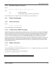
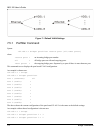
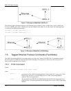
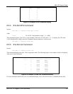
Figure 7-3 Example of Modified VLAN Port 3
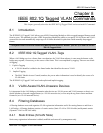
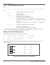
The following figure illustrates that port 1 (the Ethernet port) is linked to ports 2 (ADSL port 1) and 3 (ADSL port
2). Ports 2 (ADSL port1) and 3 (ADSL port 2) are also linked to each other. Or, in other words, the following figure
is a result of the following commands:
192.168.1.1 bridge> portfilter 2 1 3
192.168.1.1 bridge> portfilter 3 1 2
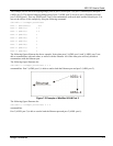
Figure 7-4 Example of Modified VLAN Settings
7.6 Tagged Ethernet Frames Commands (Fast Mode)
The ADSL Networking Module’s fast mode makes use of the “tag” subset of the IEEE 802.1Q standard to identify
the source port of an Ethernet frame and speed traffic through a service gateway. In this way, the source port of a
frame can be recognized across switches.
7.6.1 PVID Command
Syntax:
192.168.1.1 bridge> pvid [<port> <vid>]
where
<port> =
port number of the ADSL Networking Module. Port 0 is the CPU’s port, port 1 is the
Ethernet port and ports 2-9 are the bridge ports on ADSL Networking Module
modules. These are logical ports.
<vid> =
The tag number (or IEEE 802.1Q identification) that identifies the source port of an
Ethernet frame. Allocate tag numbers for all logical ports on your ADSL Networking
Module.