


ES-2108/ES-2108-G User’s Guide
Chapter 3 Hardware Overview 37
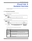
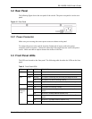
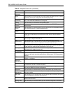
3.2 Rear Panel
The following figure shows the rear panel of the switch. The power receptacle is on the rear
panel.
Figure 15 Rear Panel
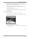
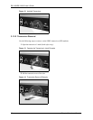
3.2.1 Power Connector
Make sure you are using the correct power source as shown on the panel.
To connect the power to the switch, insert the female end of power cord to the power
receptacle on the rear panel. Connect the other end of the supplied power cord to the power
source. Make sure that no objects obstruct the airflow of the fans.
3.3 Front Panel LEDs
The LEDs are located on the front panel. The following table describes the LEDs on the front
panel.
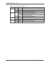
Table 2 Front Panel LEDs
LED COLOR STATUS DESCRIPTION
PWR Green On The system is turned on.
Off The system is off.
SYS Green Blinking The system is rebooting and performing self-diagnostic tests.
On The system is on and functioning properly.
Off The power is off or the system is not ready/malfunctioning.
ALM Red On There is a hardware failure.
Off The system is functioning normally.
LNK/ACT
(Ethernet
ports)
Green Blinking The system is transmitting/receiving to/from a 10 Mbps Ethernet
network.
On The link to a 10 Mbps Ethernet network is up.
Amber Blinking The system is transmitting/receiving to/from a 100 Mbps Ethernet
network.
On The link to a 100 Mbps Ethernet network is up.
Off The link to an Ethernet network is down.