


Chapter 3 Hardware Overview
GS-4012F/4024 User’s Guide
51
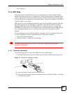
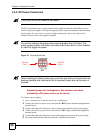
3.3.3 External Backup Power Supply Connector
The backup power supply constantly monitors the status of the internal power supply. The
backup power supply automatically provides power to the Switch in the event of a power
failure. Once the Switch receives power from the backup power supply, it will not
automatically switch back to using the internal power supply even when the power is resumed.
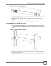
3.3.4 Powering on the Switch
1 Turn on the power supply first.
2 Turn the Switch power on second.
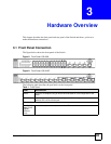
3.4 LEDs
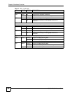
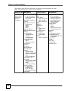
The following table describes the LEDs.
Table 2 LEDs
LED COLOR STATUS DESCRIPTION
BPS Green Blinking The system is receiving power from the backup power supply.
On The backup power supply is connected and active.
Off The backup power supply is not ready or not active.
PWR Green On The system is turned on.
Off The system is off.
SYS Green Blinking The system is rebooting and performing self-diagnostic tests.
On The system is on and functioning properly.
Off The power is off or the system is not ready/malfunctioning.
ALM Red On There is a hardware failure.
Off The system is functioning normally.
MGMT Port
10 Green On The link to a 10 Mbps Ethernet network is up.
Blinking The port is sending or receiving data at 10 Mbps.
Off The link to a 10 Mbps Ethernet network is down.
100 Amber On The link to a 100 Mbps Ethernet network is up.
Blinking The port is sending or receiving data at 100 Mbps.
Off The link to a 100 Mbps Ethernet network is down.
GS-4024 Model
Gigabit Ethernet Ports
LNK/ACT Green On The port has a successful 10/1000 Mbps connection.
Amber On The port has a successful 100 Mbps connection.
Blinking The port is sending or receiving data.
Off The port is disconnected or the link failed.
FDX Amber On The port is in full duplex mode.
Off The port is in half duplex mode or there is no connection.