


VES-1000 Series Ethernet Switch
13-4 Switch-Related Commands
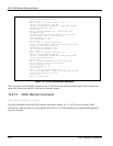
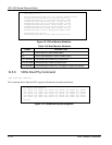
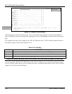
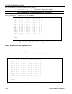
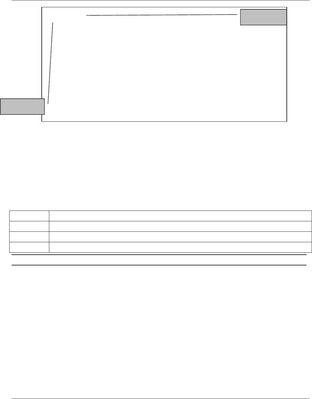
Figure 13-3 Default VLAN Settings
In this example, port 0 is the CPU port, ports 1 to 12 are the VDSL ports and ports 13 and 14 are the Ethernet
ports. The numbers in the top row denote the outgoing port for the corresponding port listed on the left (its egress
port).
This example details the VLAN settings for the VES-1012 Ethernet switch. The VES-1008 is identical however
the number of ports will only show from Ports 1-10.
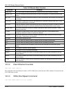
Table 13-C VLAN Key
SYMBOL DESCRIPTION
- A hyphen denotes that this port is not a member of the associated VLAN group.
0 A zero denotes the port itself.
X An “X” indicates a port’s egress (outgoing port).
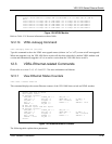
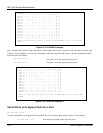
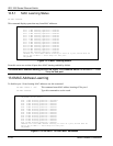
To allow two subscriber ports to talk to each other, you must define the egress for both ports.
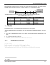
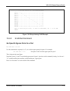
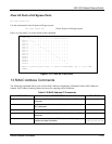
If you wish to daisy-chain the VES-1000 Series switch with for example, port 13 as the daisy-chain port (using a
crossover Ethernet cable) and port 14 as the uplink port (using a straight-through Ethernet cable), then you should
change the VLAN status to the following:
VLAN map:
0 1 2 3 4 5 6 7 8 9 10 11 12 13 14
Port 0: O — — — — — — — — — — — — X X
Port 1: - O — — — — — — — — — — — X X
Port 2: - — O — — — — — — — — — — X X
Port 3: - — — O — — — — — — — — — X X
Port 4: - — — — O — — — — — — — — X X
Port 5: - — — — — O — — — — — — — X X
Port 6: - — — — — — O — — — — — — X X
Port 7: - — — — — — — O — — — — — X X
Port 8: - — — — — — — — O — — — — X X
Port 9: - — — — — — — — — O — — — X X
Port10: - — — — — — — — — — O — — X X
Port11: - — — — — — — — — — — O — X X
Port12: - — — — — — — — — — — — O X X
Port13: X X X X X X X X X X X X X O X
Port14: X X X X X X X X X X X X X X 0
Where 'O' means the port itself, 'X' means it’s VLAN member, and '-' is not
VLAN member.
ves1012>
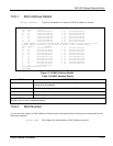
Egress port
Port numbers