


56
C
HAPTER
6: M
AINTAINING
THE
S
WITCH
4007
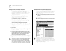
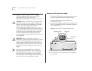
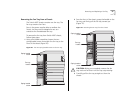
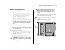
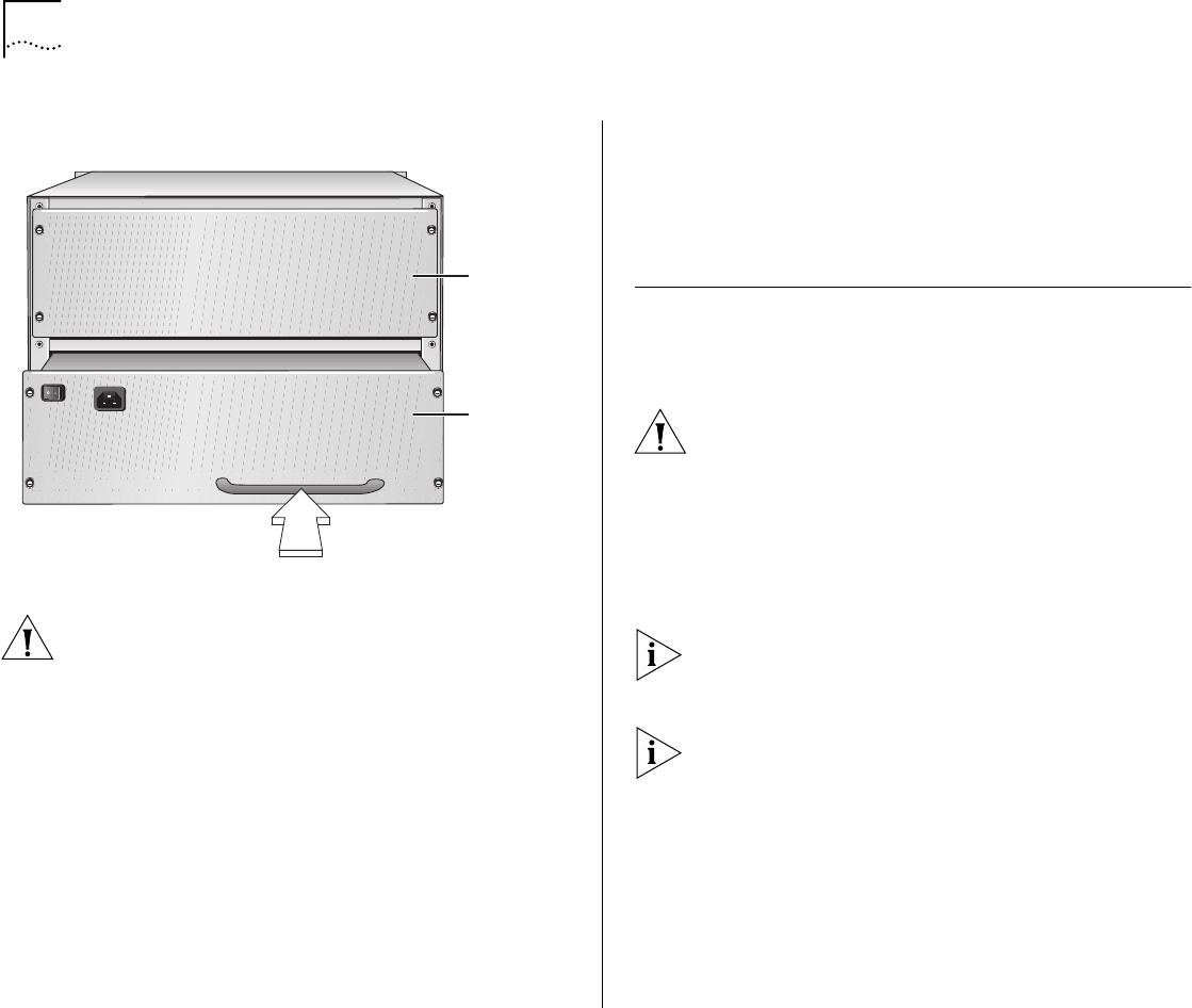
Figure 25
Installing a 930-watt Power Supply Using the
Handle
You feel a slight resistance as the connectors engage.
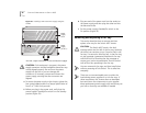
CAUTION:
If the resistance is too great, the power
supply connectors and the backplane connectors may
not be aligned properly. Do not force the power
supply into the slot or you can damage the
connectors. If necessary, remove and reinsert the
power supply, ensuring that the connectors are
aligned.
4
To secure the power supply to the chassis, tighten the
four spring-loaded screws to a Torque Specification of
from 5 to 7 in/lb (inch-pounds).
5
Before you plug in the power cord, verify that the
power supply’s Standby/On switch is in the Standby
position (Figure 24).
6
Plug one end of the power cord into the socket on
the power supply and then plug the other end into
the electrical outlet.
7
Set the power supply’s Standby/On switch to the
On position (Figure 22).
Removing and Replacing a Fan Tray
This section describes how to remove and then
replace a fan tray for the Switch 4007 chassis:
CAUTION:
The Switch 4007 sends a fan fault
message when one fan fails in the fan tray. However,
the switch can continue to run if one fan fails in the
fan tray. If a second or third fan fails, in that fan tray,
no trap message is generated. Replace the fan tray
within 48 hours of receiving the trap message or
contact your service representative. Run the switch
with all four fans operating in the fan tray.
You can remove the fan trays and then install them
without powering off the Switch. This is called
hot
swapping
.
There are no user-serviceable parts on either the
load-sharing power supplies or on the fan trays. If
these components fail, remove them as described
here and return the components to your supplier.
Keep replacement power supply units and fan trays at
your site so that they are available if needed.
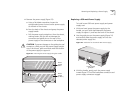
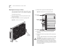
Power
supply
slot 2
Power
supply
(in slot 1)