1-10
C
HAPTER
1: I
NTRODUCTION
Sample ATM
Backbone
SwitchModule
Configurations
This section illustrates three basic configurations of the ATM Backbone
SwitchModule:
■
Basic Configuration
■
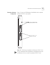
Dual-Homing Configuration
■
Dual-Homing/Module Redundancy Configuration
Basic Configuration
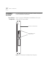
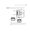
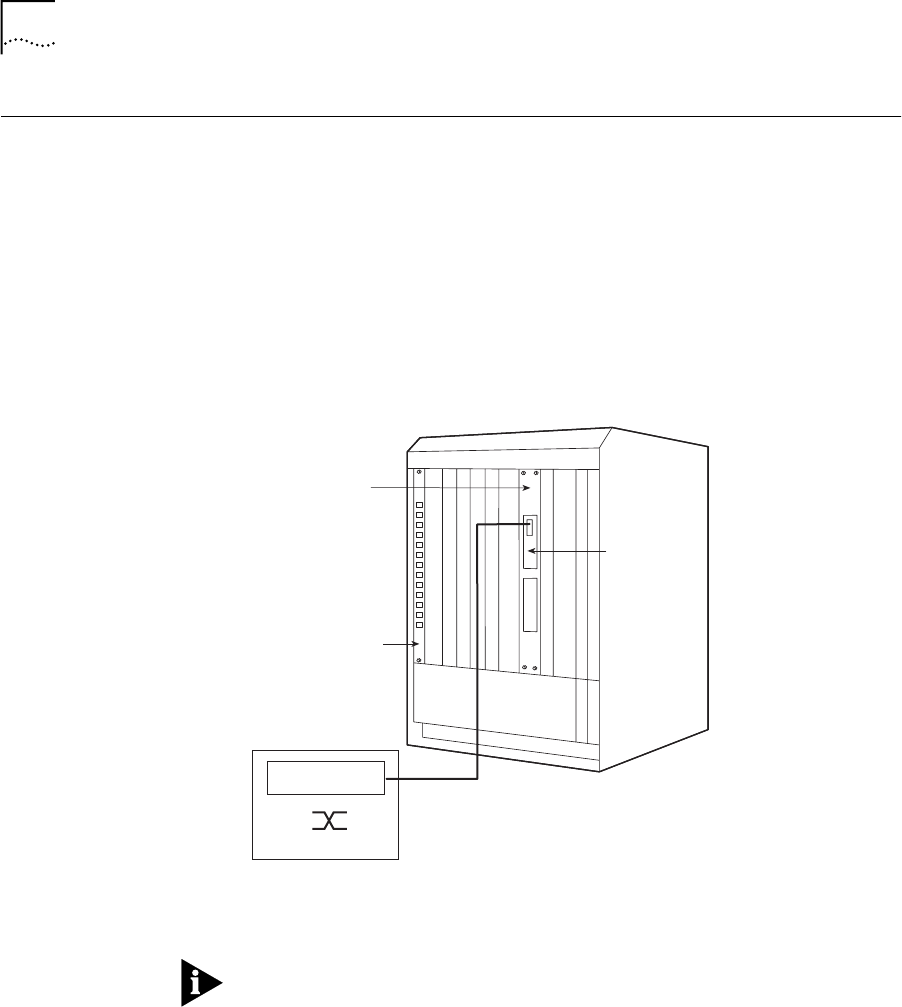
Figure 1-4 illustrates the basic configuration of an ATM Backbone
SwitchModule with only a primary ATM OC-3 card.
Figure 1-4
Example Base Configuration
See Chapter 2, LAN Emulation Overview, for a description of LAN
Emulation components and operation.
ATM Switch
Ethernet or FDDI
SwitchModule
ELANs 1 to 64
ATM Backbone
SwitchModule
Primary
ATM OC-3
LECs 1 to 64


