Sample ATM Backbone SwitchModule Configurations
1-11
Dual-Homing
Configuration
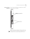
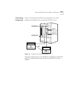
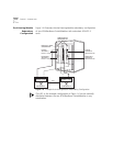
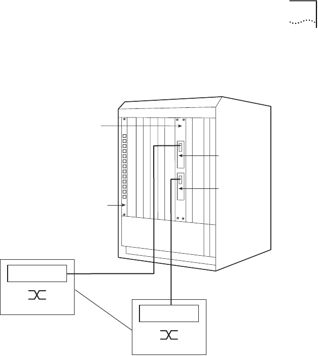
Figure 1-5 illustrates the dual-homing configuration of an ATM
Backbone SwitchModule with a redundant ATM OC-3 card.
Figure 1-5
Example Dual-Homing Configuration
If the loss of light, frame, or cell delineation is detected, the redundant
ATM OC-3 card becomes active and the primary ATM OC-3 card is
disabled.
ATM Switch A
ATM Switch B
ELANs 1 to 64
ELANs 1 to 64
Ethernet or FDDI
SwitchModule
ATM Backbone
SwitchModule
Primary
ATM OC-3
LECs 1 to 64
Redundant
ATM OC-3
LECs 1 to 64
NNI


