


Cabling Gigabit Ethernet Ports 25
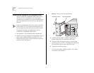
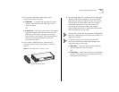
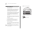
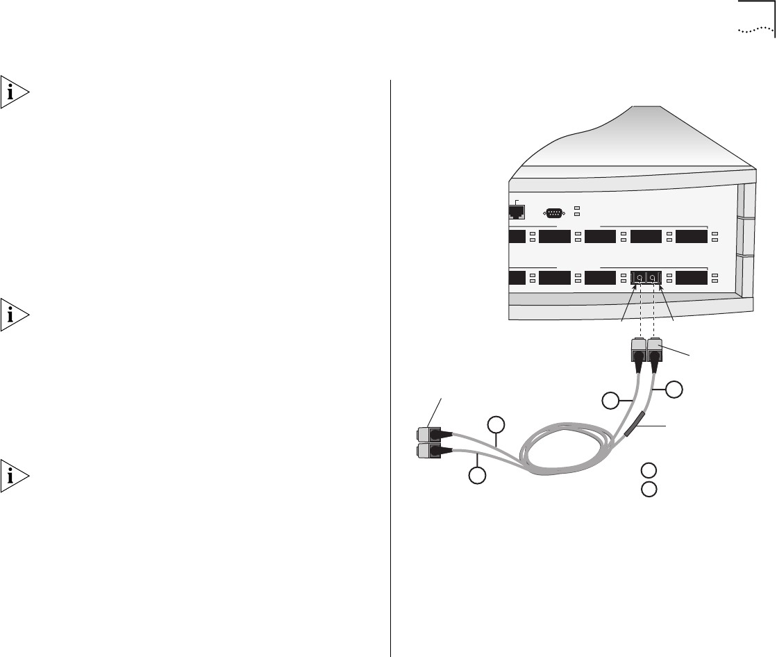
When you cable GBIC transceivers, note that the SC
Receive (RX) port is on the left and the SC Transmit
(TX) port is on the right. See Figure 9.
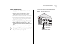
4 Insert the SC connectors on the conditioned launch
cable into the transceiver as shown in Figure 9,
ensuring that you:
■ Insert the SC connector on the multimode Receive
(RX) side of the conditioned launch cable into the
RX port on the transceiver.
■ Insert the SC connector on the single-mode
Transmit (TX) side of the conditioned launch cable
into the TX port on the transceiver.
You can think of the conditioned launch cable as an
extension to the multimode network cable.
5 Attach the other end of the conditioned launch cable
to the multimode network cable, ensuring that you:
■ Connect the multimode RX side of the conditioned
launch cable to the RX side of the network cable.
■ Connect the multimode TX side of the conditioned
launch cable to the TX side of the network cable.
If necessary, use fiber-optic couplers to connect the
male SC connectors on the multimode end of the
conditioned launch cable to the multimode network
cable.
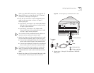
6 Attach the other end of the network fiber-optic cable
to the network device that you want to connect.
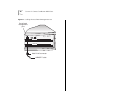
Figure 9
Connecting Using a Conditioned Launch Cable
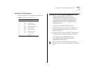
7 Repeat steps 1 through 6 for additional 1000BASE
GBIC ports.
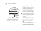
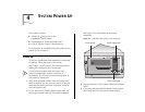
CONSOLE
0BASE TX
US PACKET
S TAT
PCKT
S TAT
PCKT
POWER
FAU LT
1000BASE (GBIC)
1000BASE (GBIC)
14 15 16 17 18
20 21 22 23 24
STATUS
green = enabled, link OK
flashing green = disabled, link OK
off = link fail
= Multimode fiber
= Single-mode fiber
A
B
RX
A
B
A
A
TX
Offset
To network
cable
SC connector