


Installation
1-17
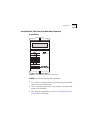
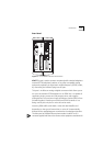
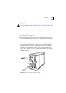
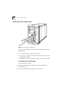
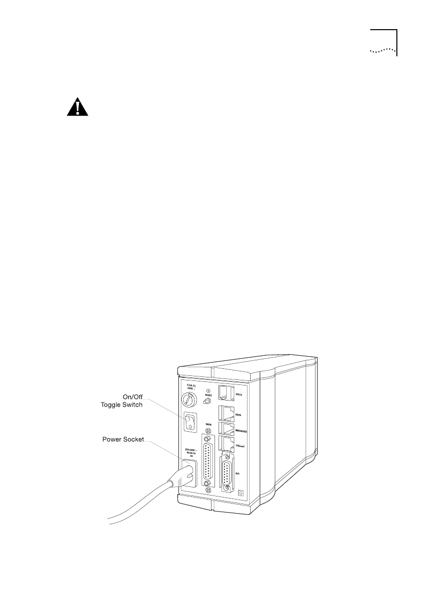
Connecting the Power
CAUTION:
First, read the section;
“Important Safety Information”
at the
start of this guide and the
“Additional Safety Information”
in
“About This
Guide”
.
Isolate the electrical mains system supply before commencing installation.
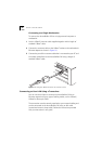
Ensure that the On/Off switch is set to its ‘OFF’ position.
1
Plug the mains lead into the power socket of the AccessBuilder 500
(see
“Rear Panel”
on
page 1-13
).
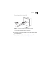
2
Plug the other end of the mains lead into an adjacent electrical mains
system outlet socket and if necessary turn on the power at the outlet
socket.
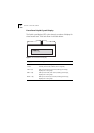
3
The AccessBuilder 500 performs a self test procedure (Figure 6.2) which
ends with the unit displaying its media access control (MAC) address
for approximately ten seconds. The display then alternates between
'NoName', with its default IP address '10.0.0.1' showing, and its port
status 'LAN 1: DOWN'. The unit's POWER and ALERT LEDs light and the
ALARM LED flashes.
Figure 1-5
Power Connection And On/Off Switch