


Chapter 3 45
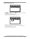
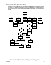
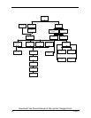
Disassembly Procedure Flowchart
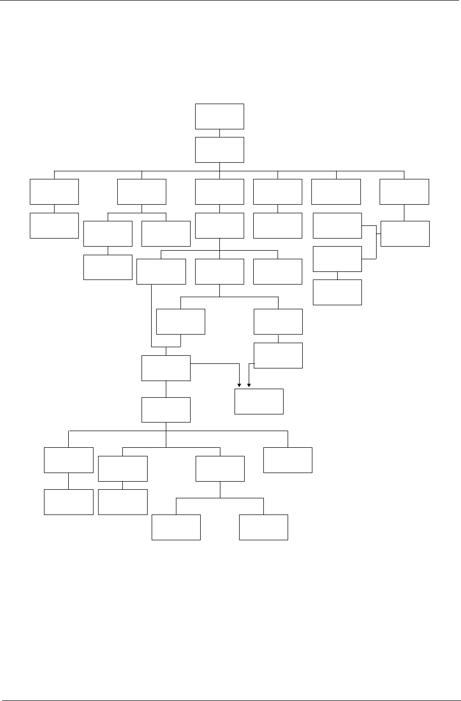
The flowchart on the succeeding page gives you a graphic representation on the entire disassembly sequence
and instructs you on the components that need to be removed during servicing. For example, if you want to
remove the main board, you must first remove the keyboard, then disassemble the inside assembly frame in
that order.
START
Battery
Video Capture
Kit Covers
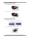
CD-ROM
Module
CD-Rom Drive
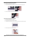
CD-ROM
Drive Chassis
Ex4
Jx2
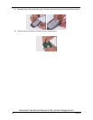
CD-ROM
Transfer Board
HDD CoverDIMM Cover
DIMM
Left & Right
Hinge Caps
Middle Cover
Modem Cover
Bx1
Modem Board
Bx2
Ax1Bx1
LCD Coaxial
Cable
Launch BoardKeyboard
LCD Cable
Cover
Fx2
Dx2
LCD Module
Ax4
LCD Bezel
Left & Right
Speakers
Gx3 (for 14.1" TFT)
Gx5 (for13.3" TFT)
Gx2
Ex4 (for 14.1" TFT)
Gx2 (for13.3" TFT)
LCD Panel LCD
Inverter Board
Gx2
Inverter Wire
Cable
LCD Coaxial
Cable
LCD Brackets
Fx4 (for 13.3" TFT)
HDD Module
HDD Bracket
HDD
HDD
Connector
Cx2
Main Unit
Microphone
Cable
CPU Heat
Sink Plate
Upper Case
Download Free Service Manual at http://printer1.blogspot.com