


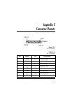

Appendix E. Connector Pinouts
88 Express XRT User Guide 61202.153L3-1
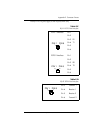
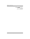
I = Input O = Output
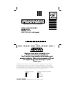
Figure E-2
Modem Interface
I = Input O = Output
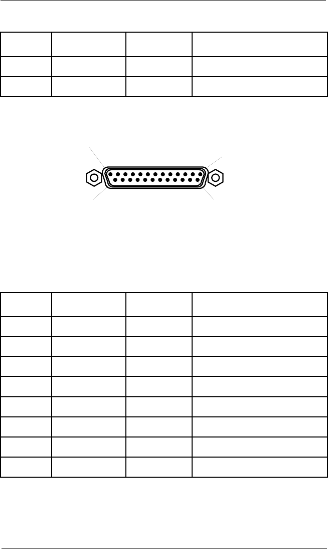
20 DTR I Data Terminal Ready
22 RI O Ring Indicator
Table E-B
Modem Interface
Pin Name I/O Description
1 Shield I/O Shield for cable
2 RD O Received Data
3 TD I Transmitted Data
4 RTS O Request to Send
5 CTS I Clear to Send
7 SG I/O Signal Ground
8 CD I Carrier Detect
20 DTR O Data Terminal Ready
Table E-A
RS-232 Interface
Pin Name I/O Description
PIN 1
PIN 13
PIN 14
PIN 25
MALE