


Chapter 2. Installation
6
Express XRT User Guide 61202.153L3-1
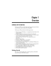
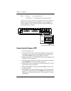
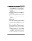
If dip switch 2 is set to the Off (up) position, the unit continues to
use the factory default settings until Switch 2 is set to the On
(down) position. Also, area code, phone numbers, SPIDS, and
stored numbers are cleared.
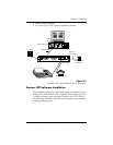
Figure 2-1
Dip Switches on Rear Panel
Connecting the Express XRT
1. Turn the computer off.
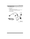
2. Using an RS-232 cable (see the section
Minimum Requirements
on page 2), connect the end with the DB-25 connector to the
port labeled
RS232
on the Express XRT rear panel.
3. Connect the other end of the RS-232 cable to an available serial
COM port on the computer.
4. Plug the small round end of the AC power cord into the jack la-
beled
POWER
on the Express XRT rear panel.
5. Place the AC power cord plug into an electrical outlet. The Ex-
press XRT is now powered on.
6. Plug the RJ-45 cable into the jack labeled
ISDN
on the rear of
the Express XRT.
7. Plug the other end of the cable into the NT1. At this time the Ex-
press XRT is powered on and the
PWR LED
should either be
flashing or on solid. See the section
LEDs
on page 71 for more
information.
SW 2: Off (up)
=
Factory Default
On (down)
=
Normal (previous settings saved)
ISDNU
OFF
ON
21
MODEMRS232POWER
1234
OFF
ON
1234