


Appendix A. AT Commands and S-Registers
64 Express XRT User Guide 61202.153L3-1
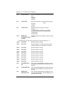
S12 ESCAPE TIME Determines the delay required immediately
before and after entering the escape com-
mand for the Express XRT to recognize and
execute the command.
Range = 0 to 127
S14 MISC BITS Miscellaneous bits (bit 8 is most significant
bit).
Bit 2 = 1:Enables on screen echo of AT com-
mands.
Bit 2 = 0:Disables on screen echo of AT com-
mands.
Bit 3 = 0:Enables AT responses from theEx-
press XRT.
Bit 3 = 1:Disables AT responses from the Ex-
press XRT.
Bit 4 = 1:Enables AT responses to be dis-
played in text form.
Bit 4 = 0:Enables AT responses to be dis-
played in numeric form.
Bit 5 = 0:Do not toggle
Bit 5 = 1:Toggle
E Bit 80 <-> BF when using V110
Bit 7 = 1:Disable PPP ACCM spoofing.
Bit 7 = 0Enable PPP ACCM spoofing.
Bit 8 = 1:Ring indicator uses cadence.
Bit 8 = 0:Ring indicator remains on.
S15
ASYNC
BOND-
ING
Asynchronous BONDING method.
0 = ADTRAN revision 0 (default)
1 = Multi-vender option
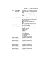
S22 MSG BITS Miscellaneous message bits (bit 8 is most
significant bit).
Bit 5= Bit 6 = Bit 7 = 1 Allows connect mes-
sage with baud rate.
Bit 5= Bit 6 = Bit 7 = 0 Connect message
without baud rate.
S25
DTR DETECT
TIME
Determines time, in hundredths of a second,
that must elapse before the Express XRT rec-
ognizes a change in DTR.
Range = 0 to 255
S27 PPP MODE Value determines whether or not PPP will
be a single-link or multilink connection.
0=Single-link operation (default)
1=Multilink operation
2=Use compression
S30 DTE CTS Controls the operation of the DTE connector
CTS line.
0=Follows RTS
1=Force CTS