


Chapter 1. Understanding ISDN and the ISU 128
61202.029L2-1 ISU 128 User Manual
3
• With DTR asserted, some bridges/routers raise DTR when bandwidth on
their dedicated line is exceeded. In high-traffic times, this allows the ISU
128 to dial out over the ISDN for an extra 128 kbps of bandwidth-on-de-
mand.
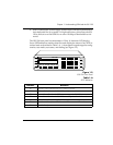
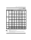
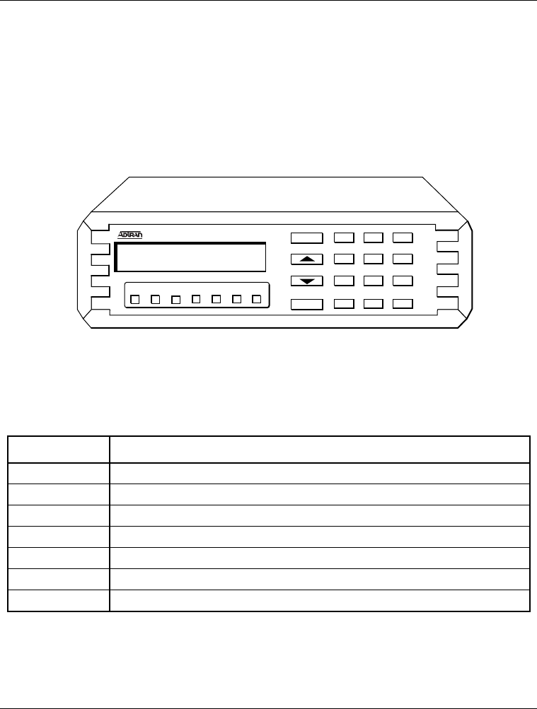
The ISU 128 front panel accommodates a 2-line, 16 character LCD display.
Seven LED indicators monitor data flow and display the status of key DTE in-
terface leads as described in Table 1-A. A front panel keypad supports config-
uration, test modes, test status, and dialing (see Figure 1-2).
Figure 1-2
ISU 128 Front Panel
Table 1-A
DTE Indicators
Indicator Definition
RS Request to Send. Indicates the DTE is ready to transmit.
CS Clear to Send. Indicates the ISU 128 is ready to transmit.
TD Transmit Data. On when the DTE is transmitting to the ISU 128.
RD Receive Data. On when the ISU 128 is receiving data from the far end.
CD Carrier Detect. On when the ISU 128 is connected to a remote unit.
TR Data Terminal Ready from DTE. On when DTR is active at DTE interface.
SR Data Set Ready.
ENTER
123
456
789
#
0
*
CANCEL
RS CS TD RD CD TR SR
ISU 128