


Chapter 3. Installation
12 ISU 128 User Manual 61202.029L2-1
DTE DATA CONNECTION
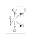
Data terminal equipment is connected to the ISU 128 by using either the RS-
530 interface, the V.35 interface, or EIA-232 interface on the rear panel of the
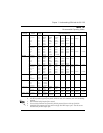
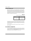
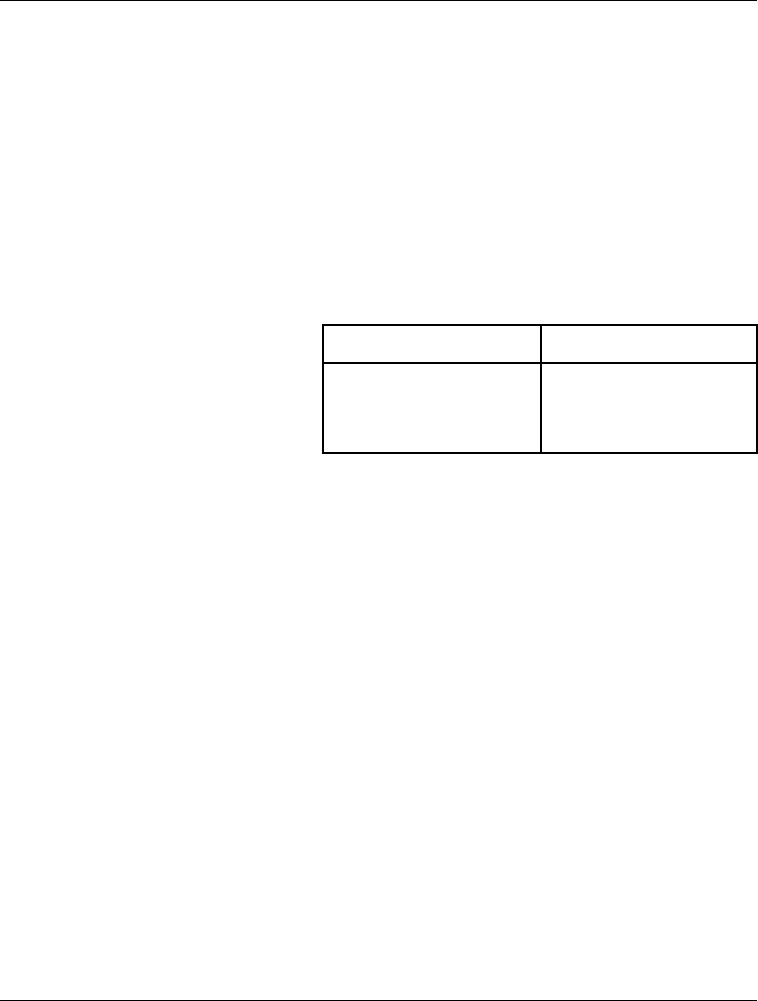
ISU 128. The maximum recommended cable lengths are shown in Table 3-A.
See the appendix Connector Pinouts for each interface pin assignments. Be sure
to configure the menu option for the connector type used in your application.
Refer to the section DTE Options for Asynchronous and Synchronous Operation in
Chapter 6 to configure the connector type.
Table 3-A
Maximum DTE Interface Cable Lengths
The RS-530 interface and the V.35 interface support data rates up to 128 kbps.
The DTE rate is configured from the front panel of the ISU 128 or by using AT
commands. See the chapter Configuration to configure the ISU 128 with the ap-
propriate data rates.
To prevent possible radio frequency interference emissions, a shielded V.35
cable is required.
DIAL INTERFACE CONNECTION
If out-of-band RS-366 dialing is required for applications such as videoconfer-
encing or FAX machines, the dialing interface of the host DTE should be con-
nected to the dial port marked RS-366/Maintenance. Pin assignments for the
RS-366 connector are listed in the appendix Connector Pinouts.
DTE Interface Max Cable Length
RS-530 50 feet
V.35 30 feet
EIA-232 15 feet