


Chapter 6. Configuration
61202.029L2-1 ISU 128 User Manual 33
V.25 bis
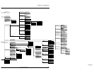
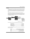
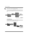
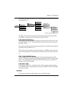
Configuring the ISU 128 for V.25 bis (see Figure 6-5) enables in-band dialing
over a DTE interface using asynchronous or synchronous V.25 bis commands.
V.25 bis can be used to establish and end a call. Disconnecting calls can also
be done from the front panel (as previously described) or from the far-end
unit.
V.25 bis dialing is used primarily by DTE with synchronous interfaces
(HDLC/SDLC or BSC/BISYNC) not supporting the AT command set, which
is commonly used by asynchronous devices. The ISU 128 supports V.25 bis in-
band dialing in accordance with Fascicle VIII.I - V.25 bis (Malaga-Torremoli-
nos 1984, Melbourne 1988).
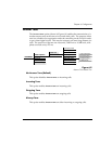
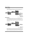
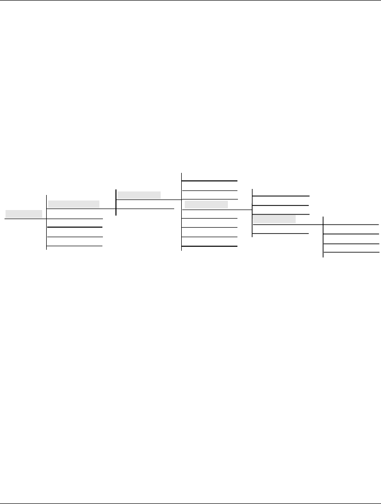
Figure 6-5
Dial Options, V.25 bis Menu Tree
Recommendation V.25 uses the following DCE/DTE control signals:
Transmitted data .......................................................... circuit 103
Received data................................................................ circuit 104
Ready for sending ........................................................ circuit 106
Data set ready ............................................................... circuit 107
Data terminal ready .................................................circuit 108/2
Calling indicator........................................................... circuit 125
The ISU 128 supports the following V.25 bis commands to control automatic
calling and answering:
CRN..................................... call request (number in command)
CRS.......................................call request (using stored number)
PRN ........................................................program stored number
RLN ..................................................................list stored number
CIC..............................................................connect incoming call
DIC ........................................................disconnect incoming call
3=CONFIG
1=Netw. options
2=DTE options
3=Protocol
4=Quick setup
5=Remote config
1=Dial Line
2=Leased Line
1=Switch protocl
2=Call type
3=Terminal ID
4=Dial options
5=Auto answer
6=Answer tone
7=Connect Timout
8=Call Screening
1=Front Panel
2=RS-366
3=AT commands
4=V.25
5=Disabled
1=V.25 HDLC
2=V.25 ASYNC
3=V.25 BISYNC
4=V.25 HDLC FLAG