Chapter 6. Configuration
61202.029L2-1 ISU 128 User Manual 35
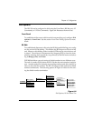
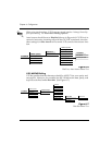
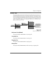
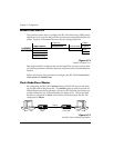
The setting in Figure 6-8 allows for V.25 bis messages in asynchronous (start/
stop) data format.
Figure 6-8
V.25 bis ASYNC Menu Tree
Although V.25 bis allows asynchronous data format, asynchronous DTE is
more likely to support the AT command set than V.25 bis.
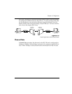
V.25 SYNC HDLC Dialing
This setting provides V.25 bis messages in bit-synchronous format (for exam-
ple HDLC, SDLC, X.25). The bit-synchronous format is the most commonly
used by V.25 bis.
This option specifies that the characters should be 7-bit ASCII, with the 8th bit
ignored (it may be either 0 or 1).
The first byte of each packet contains all ones (A = FF HEX), and the second
byte of each packet (the C byte) is either 13 HEX or 03 HEX if not the final pack-
et.
V.25 SYNC BISYNC Dialing
This setting allows for V.25 bis messages in byte synchronous format (BI-
SYNC). V.25 bis specifies that the characters should be ASCII, 7 bits, and odd
parity. This setting allows synchronous DTE which does not use HDLC to
support serial in-band dialing.
V.25 HDLC FLAG
Configuring the ISU 128 for HDLC FLAG V.25 bis enables in-band dialing
over a DTE interface using standard synchronous HDLC V.25 bis commands
with 0x7E hex idle.
Disabled
This selection disables in-band dialing over the DTE interface.
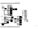
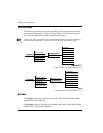
3=CONFIG
1=Netw. options
2=DTE options
3=Protocol
4=Quick setup
5=Remote config
1=Dial Line
2=Leased Line
1=Switch protocl
2=Call type
3=Terminal ID
4=Dial options
5=Auto answer
6=Answer tone
7=Connect Timout
8=Call Screening
1=Front Panel
2=RS-366
3=AT commands
4=V.25
5=Disabled
1=V.25 HDLC
2=V.25 ASYNC
3=V.25 BISYNC
4=V.25 HDLC FLAG


